Continue to Site

Welcome to EDAboard.com

Welcome to our site! EDAboard.com is an international Electronics Discussion Forum focused on EDA software, circuits, schematics, books, theory, papers, asic, pld, 8051, DSP, Network, RF, Analog Design, PCB, Service Manuals... and a whole lot more! To participate you need to register. Registration is free. Click here to register now.

Triac/Optoisolator combo - why won't it turn off?

Status
Not open for further replies.

AleXYZ

Junior Member level 3
Joined
May 12, 2010
Messages
29
Helped
4
Reputation
8
Reaction score
4
Trophy points
1,283
Location
USA
Activity points
1,697
This problem has had me pulling my hair out for 2 weeks now... it is wired up on my bench and can't find the right incantation to make it work!

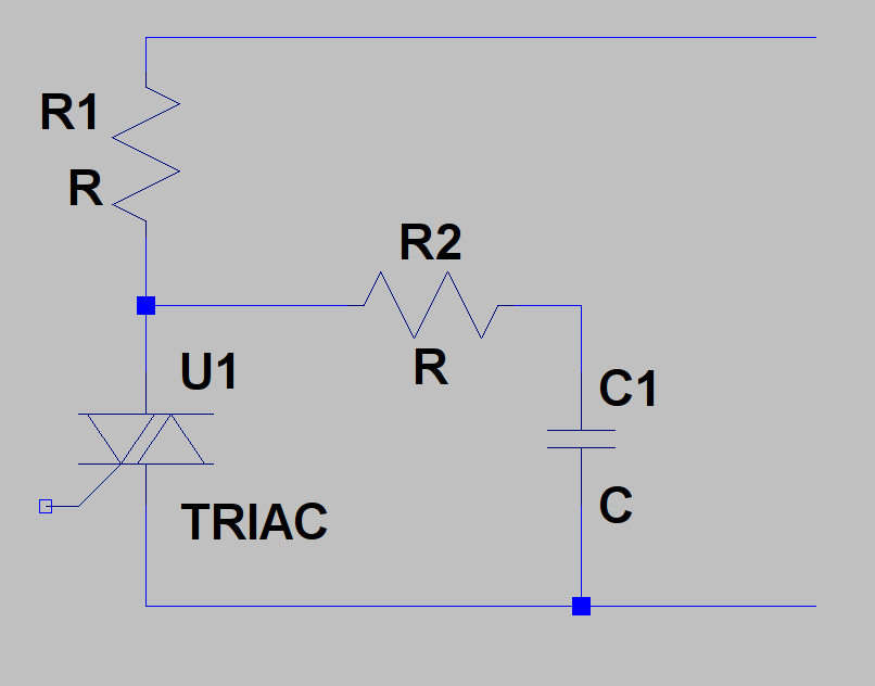
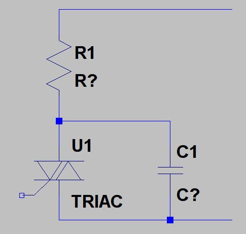
How do I do TTL level switching of a high voltage A/C circuit with the modified sine wave as shown? Should I be using something other than a triac? Is the problem that the load is capacitive?


The TRIAC (MAC97A6) turns on at power-up and will not turn off.
The optoisolator is a MOC3023.
The load currents are very small, less than 20 milliamps.
I have tried different resistor values from 100 ohms to 10k ohms.
The AC power supply is microcontroller timed, and rendered by a dual MOSFET H-Bridge off a 150v DC rail.


If you have the right answer and live within 50 miles of me I will happily buy you a case of your favourite beer!
 

I have no experience of Triacs, Diacs or SCR's and such stuff but memory says they turn off when they have 'zero current' flowing through them.

Whilst Nimeshasilva suggests a 'zero crossing' opto-isolator,

Product Folder - MOC3041-M - 6-Pin DIP 400V Zero Crossing Triac Driver Output Optocoupler, Fairchild Semiconductor - Global Leader in Power Optimization

It would seem the device looks for 'zero voltage' crossing and, as you have mentioned yourself, given the load is capacitative then zero voltage crossing will not coincide with zero current.

Having said that you might assume that if you switched things off then irrespective of what was going on elsewhere sometime they must end up with zero current going through them and therefore switch off.

Mumble mumble, either your 50uS is insufficient for the device to turn off properly before it gets hit again or, perhaps, the step voltage from your 'modified' sine wave exceeds the dV/dT rating of the device and is holding it on.

I would 'guess' that the dV/dT rating is dependant on its previous state such that if it was previously off it may not be affected by a particular value but if it was previously on then the dV/dT rating would be reduced....

Perhaps,


to slow down the dV/dT.

Conceptually I might be bothered about switching capacitative loads in this way given the opportunity for big peak currents through the device so in some respects the added series resistor will help. Unfortunately the device will still be shorting the parallel capacitor but it might not get hit so hard.

Genome.

PS, if that does work you will have to put your feet up drink the crate of beer yourself. May I recommend Timmy Taylor's Porter.
 
Genome -

YOU'RE A GENIUS!!
Putting a small C1 across the M1/M2 terminals of the triac did the trick. I didn't even try the resistor yet. I am so thrilled! (And Relieved.)

It is not a 100% solution, as yet, as I have different loads measuring from about 0.002 uF to 0.0213 uF. For the smallest load, I selected a 220 pF capacitor and it started switching perfectly. When I put the largest load, it wouldn't switch off... just like before. I'd like to have a solution that works for all loads within the range but for now I am happy that at least SOMETHING is working.


More details in a bit, after some more experimentation.....
 
glad your problem solved. :)

hey genome, shouldn't that resistor come in series with the capacitor, not in series with the triac?
the typical values for snubber are 0.1uf + 120 ohms. this works for me for most cases. and make sure to keep the snubber leakage current much lower than the required current for the load. otherwise the snubber itself will turn your load on, not the triac. (this situation had gave me a headache once)

and yes, as genome mentioned, the capacitor is shorted out when the triac is on. so better you should put a resistor or else choose a triac which has a current capability > load current + current due to capacitor short out energy
 

1500 Hz is a bit fast for a triac (generally these are even slower than SCR's), the capacitive load and the reasonably steep edges of the AC source are the reason the triac stays on, as the current does not decay to low enough values for long enough for the triac to completely turn off, and then it is hit by re-applied dv/dt which triggers it on again for the next (reverse) cycle and so on, putting a capacitor across the triac allows current to bypass the triac, thus getting its current down enabling a more positive turn off AND it lowers the re-applied dv/dt seen by the triac when the source next switches. Back to back high speed SCR's will perform better (or high current back to back mosfets or IGBT's).
Hope this provides some explanation, Regards, Orson Cart
 
Last edited:
  • Like
Reactions: AleXYZ

    AleXYZ

    Points: 2
    Helpful Answer Positive Rating
The reason for failure is the high dV/dt of the "modified sine wave". It will cause self triggering of the MOC3023, and possibly even the Triac. Placing a capacitor in parallel to the Triac isn't the recommended means, you should rather follow the suggestions in the MOC302x datasheet, see https://www.edaboard.com/threads/162207/#post686270

A opto triac with zero cosiing detector also has a considerably lower dV/dt succeptibility, but I fear, it may not work with the modified sine at all, because it relies on the supply voltage staying at a lower level for a certain period of time.

P.S.: I didn't notice the 1500 Hz point. I agree, that it's at least on the edge. 400 Hz aviation power supply works well with tríacs however. But you should have a look on the triac losses.
 
  • Like
Reactions: AleXYZ

    AleXYZ

    Points: 2
    Helpful Answer Positive Rating
The reason for failure is the high dV/dt of the "modified sine wave". It will cause self triggering of the MOC3023, and possibly even the Triac. Placing a capacitor in parallel to the Triac isn't the recommended means, you should rather follow the suggestions in the MOC302x datasheet, see https://www.edaboard.com/threads/162207/#post686270


I am not convinced the MOC3023 was self-triggering. By removing the MOC3023 and using the circuit (below) without any trigger (or capacitor), the TRIAC remained on anyways.


I really appreciate everyone's feedback and insight into dv/dt. However, reducing either the voltage OR the frequency are not options. 1500 Hz is necessary for this application, and I'd like to pump the voltage as high as 220v if possible.

My next step is to research for TRIACs with higher rated dv/dt and see if they will work better than the MAC97A6. I may also get some MOC3033M's with the zero-cross logic. But at this point I'm not convinced they'll will work better than the MOC3023.
 

I am not convinced the MOC3023 was self-triggering. By removing the MOC3023 and using the circuit (below) without any trigger (or capacitor), the TRIAC remained on anyways.
Yes, that's a clear result. I also wrote about possible self triggering of the triac before I realized the 1500 Hz issue. But be sure, that a standard MOC3023 can be easily self triggered due to it's specified maximum dV/dt of only 10V/µs. Vishay has special types that are capable of 10 kV/µs.

Standard triacs aren't much better than MOC3023 with typically 50 V/µs. NXP e.g. has a family of "high commutation" triacs with better specifications.

P.S.: Assuming, that dV/dt can be managed with suitable devices, commutation time may be a more critical problem. It depends however on the duration of the modified sine zero gap. 50 us is below the specified turn-off time even of many SCRs.
 
Last edited:
  • Like
Reactions: AleXYZ

    AleXYZ

    Points: 2
    Helpful Answer Positive Rating

Sorry, I meant to comment about the other thread. Thanks, FvM, for linking to it.

Two important notes, I am not sure either is 100% relevant but here goes:

(1) The snubber circuits for the MOC3011 indicated in the thread are for INDUCTIVE loads, not CAPACITIVE. My understanding of the snubber as an R-C network is that it is to compensate the phase current induced by the inductive load. So would it really be appropriate to add more capacitance to an already capacitive circuit?

(2) the OP of the thread indicated he resolved the problem by adjusting the firmware's PWM. In my case, both the A/C and the PWM going into the optoisolator are generated by the same microcontroller and are synchronized so that the optoisolator "off" coincides with the beginning of a zero-cross phase.

---------- Post added at 23:40 ---------- Previous post was at 23:29 ----------

...I also wrote about possible self triggering of the triac before I realized the 1500 Hz issue. But be sure, that a standard MOC3023 can be easily self triggered due to it's specified maximum dV/dt of only 10V/µs.

A good point, and my apologies, I didn't mean to disregard it.


Vishay has special types that are capable of 10 kV/µs.

Do you have a Vishay part number handy? I'd like to look at the specs.

P.S.: Assuming, that dV/dt can be managed with suitable devices, commutation time may be a more critical problem. It depends however on the duration of the modified sine zero gap. 50 us is below the specified turn-off time even of many SCRs.

Well, all I can say is that I now have the larger (0.0213 uF) load running on my bench with a 0.0082 uF capacitor across MT1/MT2, and it has been PWM'ing away for almost an hour now with no sign of smoke. The scope says it is running about 1350 Hz and the DC voltage rail going into the H-Bridges is at 164 volts. I shut down the circuit for a moment to see if anything was even getting hot: both the Opto and the TRIAC are room temperature.

Maybe I'll run it for a few more hours (it's so beautiful to see this circuit working finally!!!) but right now it doesn't look like it's going to fail.
 

I just wanted to quote the circuit, not refer to other details of the previous thread, that in fact may be irrelevant here.

The general point is, that a RC snubber helps to reduce the dV/dt for the opto triac and the main triac as well. This is particularly a problem with inductive loads, that create extra dV/dt during commutation. But I also experienced a case, where a snubber was necessary to keep a MOC3020/triac combination from self triggering respectively make it commutate with a pure resistive load - with a power supply of unusual high harmonic voltage level. But the snubber effect would be actually dwarted by a capacitive load, at least for the main triac.
 

1500 Hz is a bit fast for a triac (generally these are even slower than SCR's), the capacitive load and the reasonably steep edges of the AC source are the reason the triac stays on, as the current does not decay to low enough values for long enough for the triac to completely turn off, and then it is hit by re-applied dv/dt which triggers it on again for the next (reverse) cycle and so on, .... Back to back high speed SCR's will perform better

This is also a great suggestion. I will try a back-to-back SCR configuration and see if that can allow me to remove the cap. Right now I am not able to power the load off completely when the TRIAC is off, because (obviously) I have a capacitor divider circuit across the power supply and both caps (load+buffer) consume power. Also, as it is now I have to tune the buffering capacitor for the size of load, which is undesirable for the application.
 

"Genius"? Well not really, just a guess. I see you are getting some good answers from others with more experience. It looks like you will probably be using a different set up but, again being a novice, if the power losses are acceptable and the device is capable of turning off in the 50uS period, which seems unlikely....

Doing sums,


Just assume that your 220V is applied with zero rise time. Then the current in R1 is 220/R1 giving you a dV/dT in the capacitor of

dV/dT = 220/R1.C1

and pick values to match that to the dV/dT rating of the triac. Pick R2, don't know, 1/10 of R1 to limit current when the Triac turns on and discharges C1. I'm not sure how things would look in terms of power losses but at least that should give you a starting point for calculating reasonable values which will 'work' irrespective of the load.

Of course those values may not turn out to be reasonable.

Genome.
 

Total voltage seen by triac, don't forget that the triac sees the 2 x the source volts every time the source switches (unless the source is a short during the 0V region) due to the voltage from the charge stored on the load cap adding to the newly reversed source voltage, so possibly 300V in a small fraction of a uS applied to the triac every switch to rail of the inverter source.

Regards, Orson Cart
 
Last edited:

Total voltage seen by triac, don't forget that the triac sees the 2 x the source volts every time the source switches (unless the source is a short during the 0V region) due to the voltage from the charge stored on the load cap adding to the newly reversed source voltage, so possibly 300V in a small fraction of a uS applied to the triac every switch to rail of the inverter source.

Regards, Orson Cart,

Yes, sorry... my bad. Perhaps, overall, given the capacitative nature of the load and the driving waveform it would be wise to check that the repetitive surge rating of the device is not being exceeded. I would not know which part of the data-sheet would reference that one..

Genome.
 
Last edited by a moderator:

I wonder, if you considered photovoltaic solid state relays. There's a rich choice from various manufacturers in the high voltage (400 V) and low current range (up to 1 A). Clara has also high voltage types rated for more than 10 A. But due to limited curent provided by the photovoltaic principle, the switching speed is low.


The Vishay phototriac types are listed in the below appended application note.

P.S.: If I understand right, maximum load currents are a few 10 mA in your application. Currents up to 100 or 200 mA can be handled by a photo triac alone.
 

Attachments

  • phototri.pdf
    414.6 KB · Views: 259
Last edited:
  • Like
Reactions: AleXYZ

    AleXYZ

    Points: 2
    Helpful Answer Positive Rating
I would be inclined to add a resistor between the gate and MT1 so when the opto turns off the gate isn't left floating.

Brian.
 

I would be inclined to add a resistor between the gate and MT1 so when the opto turns off the gate isn't left floating.

Sorry, this doesn't make sense to me. If a triac is a pair of oppositely oriented SCR's with a common gate, then isn't tying the gate to either MT1 or MT2 with a resistor the same as having one of the SCR's on all the time?
 

A triac isn't exactly the same as two SCRs but ignoring that, if what you say is true, when the opto started to conduct, only one of the SCRs would work anyway, it would have to be connected to the other MT pin to to make the second SCR work.

The point I'm making is that the triac is susceptible to false triggering if the gate is left open circuit. There will be a small leakage current to it and especially when handling high(ish) frequency spikes, it will suffer from capacitive coupling. A resistor to discharge the leakage and prevent the gate floating would in my opinion be a good idea. Remember that when the opto is turned off, it is effectively open circuit, leaving the gate disconnected.

Brian.


Status
Not open for further replies.

Part and Inventory Search

Welcome to EDABoard.com

Sponsor

Back
Top