Continue to Site

Welcome to EDAboard.com

Welcome to our site! EDAboard.com is an international Electronics Discussion Forum focused on EDA software, circuits, schematics, books, theory, papers, asic, pld, 8051, DSP, Network, RF, Analog Design, PCB, Service Manuals... and a whole lot more! To participate you need to register. Registration is free. Click here to register now.

Opto current needed to stop switching in flyback?

Status
Not open for further replies.

eem2am

Banned
Joined
Jun 22, 2008
Messages
1,179
Helped
37
Reputation
74
Reaction score
24
Trophy points
1,318
Activity points
0
Hello,

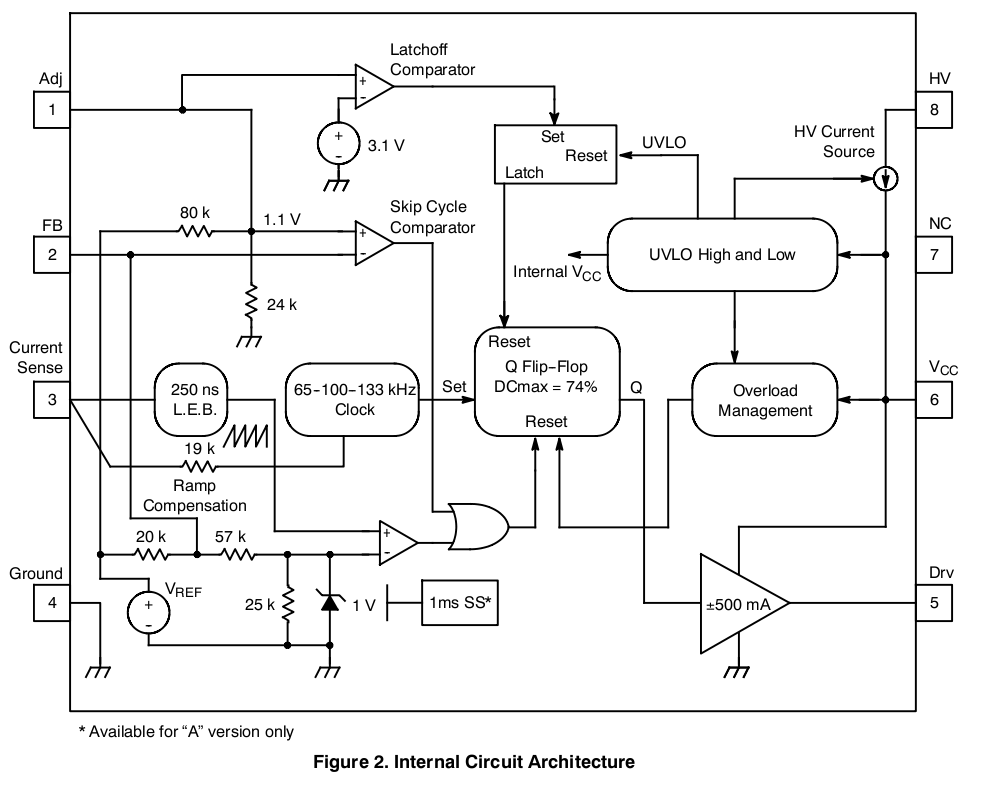
I am using NCP1217 to do a 20W offline flyback.

The feedback uses an opto-coupler connected as in page 2 of the NCP1217 datasheet.

Looking at the block diagram on page 3 of the datasheet, is it correct to say that the opto-transistor only has to draw 200uA from pin 2 in order to completely stop switching in the NCP1217?

NCP1217 DATASHEET:
https://www.onsemi.com/pub_link/Collateral/NCP1217-D.PDF
 

The block diagram shows,


With 1.1V at the input to the 'Skip Cycle' comparator and the 80K/24K divider then Vref should be about 4.77V. Bringing FB below that 1.1V level will 'Skip Cycles' or rather disable the IC so 3.7V across 20K would be 185uA. Of course if you change the voltage on the ADJ pin things will vary accordingly.

If you were to short ADJ to ground then shut down would require 4.77V/20K or 240uA although your opto-coupler transistor might not 'saturate' to that level. That may, in part, be why the 'Skip Cycles' is there an addition to any other function it performs.

Genome.
 
Last edited:
  • Like
Reactions: eem2am

    eem2am

    Points: 2
    Helpful Answer Positive Rating
Status
Not open for further replies.

Similar threads

Part and Inventory Search

Welcome to EDABoard.com

Sponsor

Back
Top