Continue to Site

Welcome to EDAboard.com

Welcome to our site! EDAboard.com is an international Electronics Discussion Forum focused on EDA software, circuits, schematics, books, theory, papers, asic, pld, 8051, DSP, Network, RF, Analog Design, PCB, Service Manuals... and a whole lot more! To participate you need to register. Registration is free. Click here to register now.

High Speed High Voltage Level Shifter

Status
Not open for further replies.
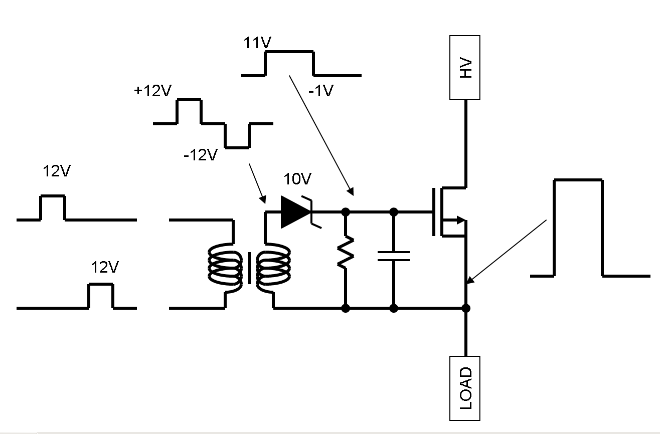
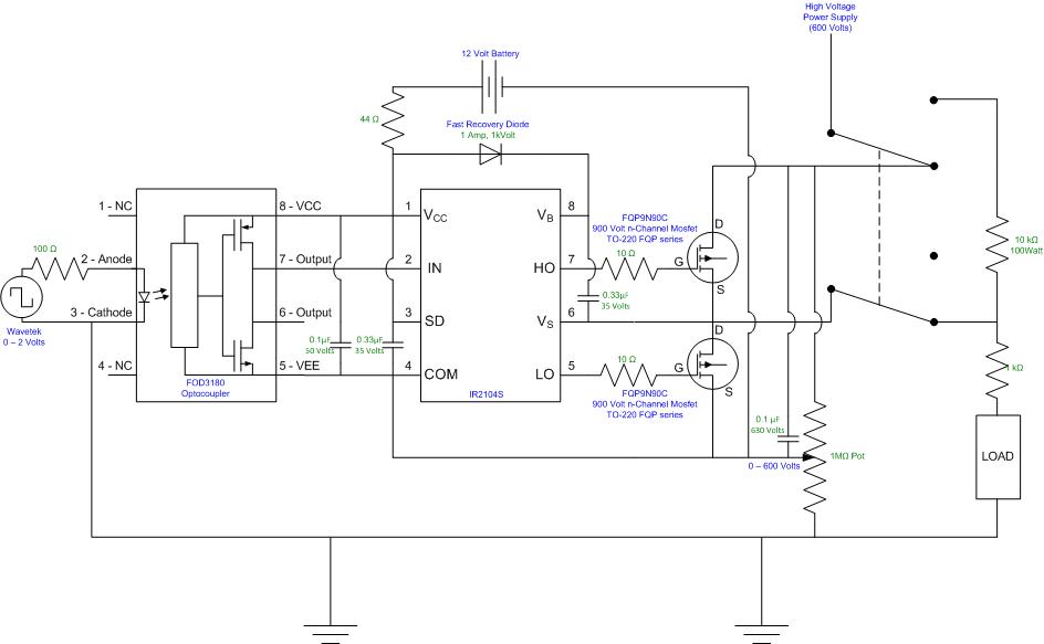
Your missing the voltage translation on the OP input. Also I don't see, how the said "phantom powering" should work, except from the input signal through parasitic diodes. But it would be too low in this case.

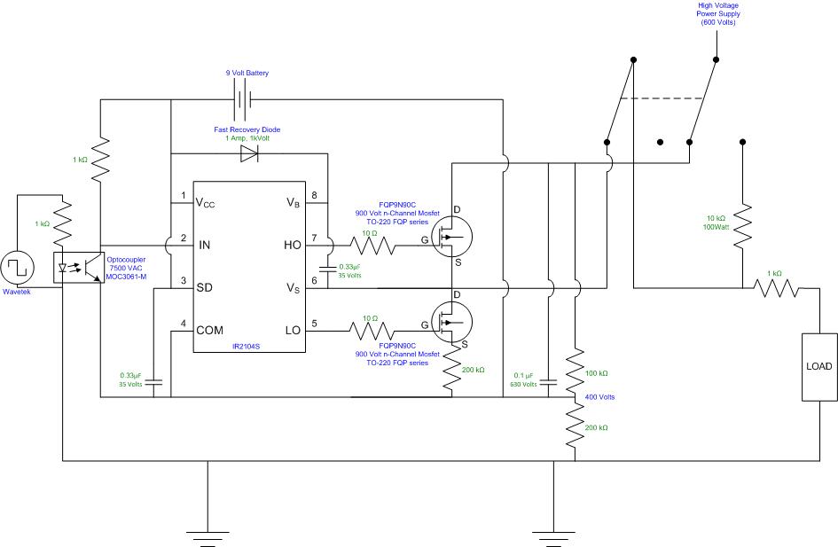
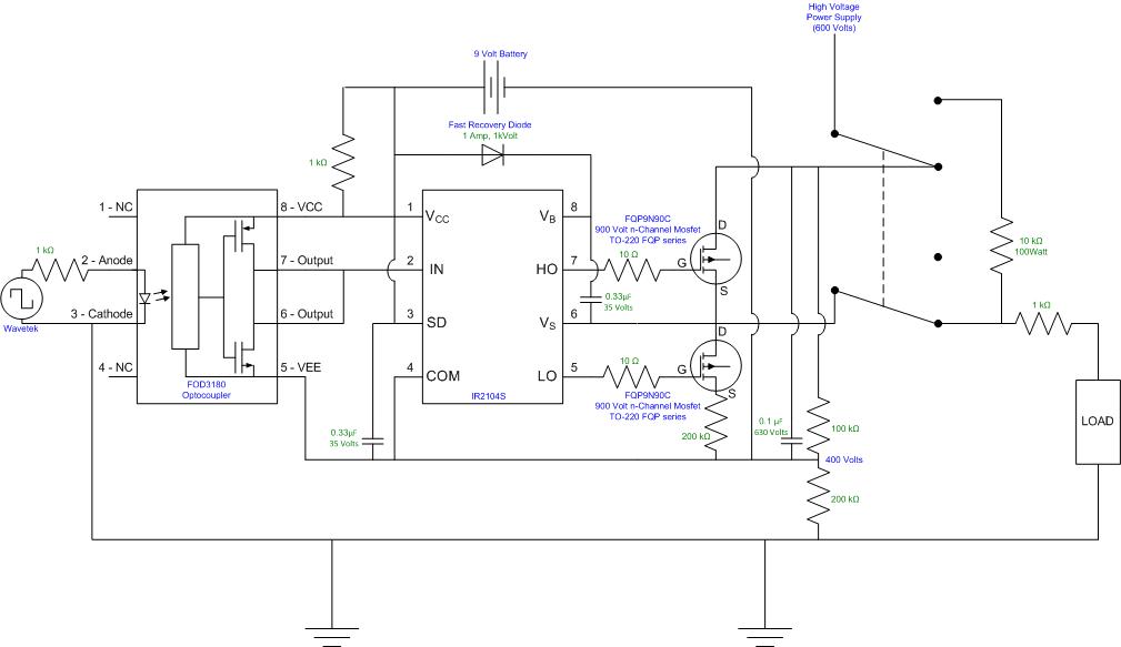
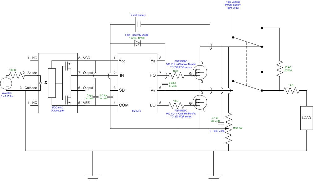
Operating the IR2104 on top of the 400V is basically a good idea, but would need a suitable level shifter or fast opto coupler on the logic input. And a floating power supply, e.g. by a galvanically isolated DC/DC converter.
 
Your LH time is simply (Cdd+Cstray)*Rload. Nothing to be
done about that. Other than to make a push-pull stage so
that you don't have to have a loussy pullup to obtain low
power.

At this kind of offset, if you have the certainty of switching
density I'd be looking at a pulse transformer gate drive on
the high side. Bridge the primary across a pair of FET drivers
with a nonoverlap waveform. Feed the secondary through
a zener diode so that forward charges the gate, and negative
returns the gate to zero or slightly negative. You only need
enough pulse time to charge / discharge the gate storage
cap, which needs to ride out the cycle with little droop. A
safety resistor for DC is not a bad idea.


Freebird - Thank you for your reply. We have been able to fix this problem by using the IR2104S suggested by FvM and two n-Channel Mosfets. Our current issue is we are trying to produce a half or partial pulse (ex. 600 to 400 Volts). FvM also suggested using an optocoupler to produce this wave and we believe we can with the circuit ngm posted above.

FvM - Do you think this circuit looks right??

Ngm - Are there any other optocouplers we should experiment with?
 

The optocouplers we used didn't work that well. The optocopulers were triac's and were specifically designed for AC purposes. As our goal is DC pulsing, we switched to a FOD3180; its a high speed mosfet pair. See circuit diagram below, any input would be appreciated.


The FOD3180 optocoupler would be capable of driving MOSFETs directly, to drive a IR2104, a regular high-speed digital optocoupler should work as well. But it's basically O.K.

But I have two doubts:
- IR2104 has a specified undervoltage-lockout threshold around 9 V (up to 9.8 V), it's not necessarily working with a 9V battery.
- I don't understand the purpose of the 200 k resistor at the source terminal of the low-side MOSFET. If you want to apply current limiting resistors, they should be placed at the drain terminal. But 200 k is much too high anyway, I think.
 
FvM - Thanks for the quick response.

1. The recommended VCC conditiosn for both the FOD3180 and IR2104 is 10-20volts. I can replace the 9volt battery with a 12volt or 15volt battery. Do you think this will be fine?
2. Your absolutely right about 200kohm resistor, i'm going to replace that with a wire.

I'm going to put this together now and see what happens. I'll let you know how it turns out.

---------- Post added at 15:12 ---------- Previous post was at 15:06 ----------

FVM - thanks for the quick response

1. The IR2104 and FOD3180 both have VCC recommended operating conditions of 10 to 20volts. I have a 12volt and 15 volt battery i can put in place of the 9 volt. what do you think?
2. Your absolutely right, that 200kohm is a mistake and I will replace it with a wire.

I'm going to put this circuit together now and test it out. I'll let you know how it goes.
 
We also caught the unnecessary 1k between the 9V and Vcc of the coupler and IR2104S. That was left over from a previous coupler design...
 
  • Like
Reactions: cheeseb332

    V

    Points: 2
    Helpful Answer Positive Rating

    cheeseb332

    Points: 2
    Helpful Answer Positive Rating
We also caught the unnecessary 1k between the 9V and Vcc of the coupler and IR2104S. That was left over from a previous coupler design...
Right, that's another design fault.
 

I connected this circuit, but I'm still not seeing the results I want. I did however notice that the 1Mohm Pot's resistance is changing. This seems to be connected to the Battery and the Wavetek. I'm not sure where but I think a resistor needs to be put in the battery's circuit somewhere. I could put a 1kohm between the fast recovery diode and the positive side of the 12volt battery.

I'm not sure if this is the only problem, but I have seen the pulsing side, and optocoupler work individually so i'm not sure what the problem could be while it's together. Please see the attached diagram and let me know of any ideas. I will continue testing the circuit.


Yes there's a (possibly minor) problem. IR2104 will draw typically 50 uA bias current from the HV supply, respectively load the potentiometer with this current. See datasheet Figure 16A and 16B. In addition, you have to check, if the MOSFETs have a leakage current. Of course, the circuit can only work with a pure capacitive load << 0.1 uF, otherwise you'll need a lower impedance power supply.
 
Hey Everyone, just wanted to give you the completed circuit. Everything works great. With this circuit I can supply DC, pulsed DC or partial pulsed DC up to 630volts. I believe this can go higher for the partial pulse as long as the difference is less than the 630volts.

Thanks everyone for your help!!!


Status
Not open for further replies.

Similar threads

Part and Inventory Search

Welcome to EDABoard.com

Sponsor

Back
Top