Continue to Site

Welcome to EDAboard.com

Welcome to our site! EDAboard.com is an international Electronics Discussion Forum focused on EDA software, circuits, schematics, books, theory, papers, asic, pld, 8051, DSP, Network, RF, Analog Design, PCB, Service Manuals... and a whole lot more! To participate you need to register. Registration is free. Click here to register now.

Discrete FET driver turns off slowly.

Status
Not open for further replies.

eem2am

Banned
Joined
Jun 22, 2008
Messages
1,179
Helped
37
Reputation
74
Reaction score
24
Trophy points
1,318
Activity points
0
Hi,

I have come up with two cheap FET gate driver circuits for driving the gate of a power mosfet in a switch mode solenoid driver.

The PWM signal is provided by the output pin of a microcontroller.
The solenoid current is 200mA.
The FET Vgs(th) should be between 0.8V and 3.5V


****************
Complimentary pair gate driver schematic:-
https://i56.tinypic.com/2zh136o.jpg

...the above "Complimentary pair gate driver schematic" gives a slow turn off of the FET since there is a lingering Vce(sat) voltage of the PNP BJT.

...here is the FET gate voltage showing the slowly declining FET gate voltage at turn off..........................

FET gate voltage with complimentary pair drive:-
https://i52.tinypic.com/xn5h8z.jpg

.....in order to make the FET turn off quicker, the following adjustments were made.................


*******************
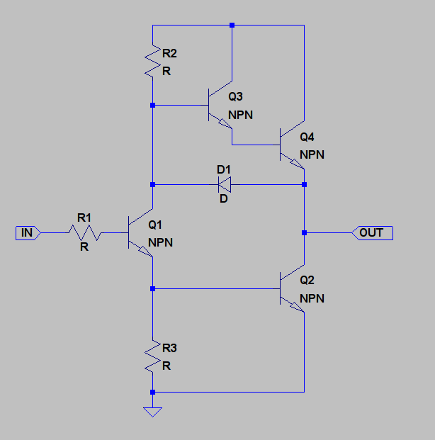
Adjusted Complimentary pair gate driver:-
https://i55.tinypic.com/v7t5sj.jpg

having the diode D2 in the Adjusted Complimentary pair gate driver gives a faster turn off of the FET.

..................the diode D2 in the "Adjusted Complimentary pair gate driver" also ensures that there is no shoot-through current by 'slamming' off the PNP BJT when the NPN conducts.

I assume that since the driver devices are BJT's, they will offer more resilience to transients coupled through the Drain-Gate capacitance than circuits which directly drive the FET from the microcontroller port.?

(its my belief that its FET gates that are the most susceptible thing to damage by transients and ESD....BJT's are more robust?)


Does any reader know of a technique of adjusting the above schematics so as to make the FET gate voltage go to zero quicker when turn-off occurs?
 

Hi

I have made a few simulation with your circuit (normal Complimentary pair gate driver), i have noticed the slow falling edge of the gate voltage as you said,
this seems to be greatly minimized (by a factor of 5) if you use a 1k pull down resistor in the gate instead of the 10k, maybe it will suite you this way instead of the modified circuit.

Alex

---------- Post added at 19:39 ---------- Previous post was at 19:33 ----------

i have also noticed that this slow falling edge part of the gate signal is at a very low level , about 0.5v and below as shown in your graph,
the output is probably not affected by that anyway because the mosfet is already turned off at that voltage, so it shouldn't matter.

Alex
 
  • Like
Reactions: eem2am

    eem2am

    Points: 2
    Helpful Answer Positive Rating
I wouldn't say much... Spice is hurting my head today... but the 'classic' 'Totem Pole' driver is something like this,


https://focus.ti.com/lit/an/slua054/slua054.pdf

It's been a long time since I looked at it so I can't remember all the reasons why other than NPNs are faster than PNPs and the diode is there for a reason.

Of course it is more complex than your solution.

Genome.
 
  • Like
Reactions: eem2am

    eem2am

    Points: 2
    Helpful Answer Positive Rating
...the above "Complimentary pair gate driver schematic" gives a slow turn off of the FET since there is a lingering Vce(sat) voltage of the PNP BJT.
I don't see slow turn off. The gate voltage is falling fast to about 0.4V. There's possibly a problem with very low threshold voltage FET's. With FDS4959, it isn't.

I think, the simple circuit is just O.K.
 
  • Like
Reactions: eem2am

    eem2am

    Points: 2
    Helpful Answer Positive Rating
How cheap does it have to be? You can get a FET driver that's
ready to go for under $2 (qty, 1). And a 500mA "relay driver"
with 4 channels per package is under $5, forget the FET.
There's a reason for these parts - look at cost in terms
of the total BOM before you get all happy about using a
50-cent transistor times 2, plus passives, plus power FET,
per channel.
 
  • Like
Reactions: eem2am

    eem2am

    Points: 2
    Helpful Answer Positive Rating
..four of the FETs that we are currently using (STB16NF06LT4 by st.com) costs $1.54 in total.

...i would like the eventual solution to be cheaper than this

as such , i am noticing that 4 cheap, small FETS (IRLML2060) and two dual FET driver IC's (Clare IXDN602SIA) COSTS $1.36 in total...............

I have looked for a cheaper x4 solenoid driver but can't find one.


i am now not so keen on super-cheap, 2N3904 type discrete solutions because you get massive tolerance on the hFE parameter......and would need to test with the lower hFE tolerance....but may have difficulty actually finding one at the lower end of the hFE tolerance band.#

Gate driver IC's don't seem to be available at prices less than 0.25 US $ per 5000 pieces (per channel, so to speak, since the Clare device is dual channel)

as well as the above Clare device, i find the next cheapest gate drivers are:

ZXGD3001
NCP3420

Its interesting that there are no really cheap, gate driver IC's with output current up to 350mA and Vin = 4V or above...

.....that's all i need, but all the market seems to sell is expensive 1 Amp plus gate drivers, with Vin = 10V or above.
 
Last edited:

I wonder, what's the purpose of using 16A FET's with 200 or 500 mA solenoid currents? As a result the switching losses caused by transistor capacitances and even the gate driver losses will be considerably higher than the FET on-state losses. Schottky diode losses are at least tenfold larger anyway.
 
  • Like
Reactions: eem2am

    eem2am

    Points: 2
    Helpful Answer Positive Rating
I wonder what are the amazing high frequencies the solenoids must be driven that a simple TIP122 (or a smd darlington) and a base resistor can´t be used. Even a BC337 can do it with 5mA base current worst case.
 

The circuit is probably used with 20KHz switching frequency,
this was the simulation switching frequency in both this and a previews thread.

eem2am, is this the switching frequency you will be using?

Alex
 
  • Like
Reactions: eem2am

    eem2am

    Points: 2
    Helpful Answer Positive Rating
The circuit is probably used with 20KHz switching frequency,
this was the simulation switching frequency in both this and a previews thread.

eem2am, is this the switching frequency you will be using?

Alex

Solenoids can be driven at fairly low speeds. I used to drive 1.6A solenoids at 200Hz. A TIP does the job and runs cool. As a bonus, you can decrease the latching time by increasing the duty cycle for a few ms.
 

Have you considered simply using a small logic-level FET
with direct drive from the uC?

I've recently built a pulsed-load jig for my work that used
the STS10DN3LH5, two channels in an 8-pin SOIC and
used a 74AC14 to drive them. The gate capacitance is
not large. I think they are 30V FETs and they can take
10A. $1.23 for 2 channels (Qty 1), $0.58 (1000).

Consider that a 74AC14, or perhaps one of the octal
or quad bus drivers, may be entirely suitable for driving
logic level FETs. A lot of these parts have 24mA at 0.5V,
meaning about 250mA peak as a driver would rate things.
And you can parallel channels without issue. My setup, I
used one Schmitt channel to drive the other 5 and paralled
those outputs to drive the two FET gates in a package.
That's about $2 for a 20A low side switch. Glue logic is
dirt cheap.

If you put a gate resistor such that peak current is
maybe 2X the rating VOL@ current, it ought to not
bother the controller any. For a 5mA driver, maybe a
500-ohm series resistor. At 475pF Ciss that would be
a 250nS time constant, way more than fast enough.
You probably don't need the resistor, but it would
keep ground / supply spiking down which could help
any analog accuracy concerns (if you have such
onboard).

I'm sure there are some with higher voltage, lower
current and I bet lower gate capacitance within this
family.
 
  • Like
Reactions: eem2am

    eem2am

    Points: 2
    Helpful Answer Positive Rating
i agree with logic level mosfet solution. cheap stuff and fairly reliable and 74C14 will handle most problems associated with connection between power and digital grounds. i used this for a similar circuit you are describing except my frequency was not static as i used the circuit as an "ON/OFF" switch... but otherwise worked great, reliable and cheap.

a 1K resistor on a mosfet gate-to-source is useful if the state during loss of power is undetermined (depends on what is driving the mosfet). at least you can drain the mosfet into an OFF state with the resistor.

Mr.Cool
 
  • Like
Reactions: eem2am

    eem2am

    Points: 2
    Helpful Answer Positive Rating
The solenoids are being driven at 22KHz switching frequency.....the duty cycle is 27%.....the duty cycle is obviously a bit more for initialisation.

I need to ask the software guy to code me up a board so i can test it and see why the switching frequency needs to be so high.


The thing about using 74 series gate outputs in parallel is that each gate would need its own series resistor, rather than being able to use one overall series resistor.....this is because they have no output current clamping and each output does not necessarily come on at the same time.
 
Last edited:

I would expect a 10nS CMOS logic gate quad / hex / octal
to match within 1nS and 10% Iout per channel. You won't
see that time-domain contention (if any) as anything other
than a broader than normal Icc spike.

After all, what is a CMOS power MOSFET driver anyway,
besides parallel fingers distributed across a big die?
 
  • Like
Reactions: eem2am

    eem2am

    Points: 2
    Helpful Answer Positive Rating
agreed with above. is usually sufficient to use a single gate resistor. or two gate resistors with a diode on the second one so you can individually control ON vs. OFF resistance.

you might want to askyour software guy to put a minimum duty cycle function. if commanded ON, then you should have a min duty cycle that allows the device to fully saturate before it is commanded OFF. this is because you don't want a permanent low duty cycle repeating forever which will overheat the mosfet (big losses in linear region of mosfet). similarly, a maximum duty cycle is useful if passing DC through your mosfet is bad (i.e. 100% dutycycle for 10 minutes). see what i mean?

Mr.Cool
 
  • Like
Reactions: eem2am

    eem2am

    Points: 2
    Helpful Answer Positive Rating
i am now not so keen on super-cheap, 2N3904 type discrete solutions because you get massive tolerance on the hFE parameter......and would need to test with the lower hFE tolerance....but may have difficulty actually finding one at the lower end of the hFE tolerance band.#

The minimum hfe in the datasheet is 30 , even at that gain the output with the 10mA you are giving to the base would be 300mA.
This rating is higher from the parallel logic gates solution and is also cheaper.

The problem is that the 2N3904 has a max collector current rating of 200mA so you should either limit that or use different transistor(s) that can provide up to 0.5A or 1A pulses.

You could use something like:
8550S
8050S

Alex
 
  • Like
Reactions: eem2am

    eem2am

    Points: 2
    Helpful Answer Positive Rating
eem2am -

I have read through this thread and the many suggestions offered, but I am still a bit confused.

I see that you are concerned about the gate drive not going to 0V from .4V quickly, but as others have already pointed out, the MOSFET is turned off at this point anyway.

What exactly is the problem you are trying to resolve? A part getting too hot, slow closing of the solenoid after PWMing, ...? Thanks
 
  • Like
Reactions: eem2am

    eem2am

    Points: 2
    Helpful Answer Positive Rating
Basically we just want to drive switch-mode solenoid fets from a microcontroller...using a cheap method.

At the moment we are driving the fet directly from a microcontroller output, which results in repetitive overcurrents from the uC output.

we think the uC will fail in time because of overcurrent.


here is the original problem:
https://www.edaboard.com/threads/199039/
 

I think that this has gotten way more complicated than it needs to be (too many chefs?). Just place a suitable value resistor between the uC and the MOSFET (470?). Where do you see a problem with doing just this? And why are you PWMing this solenoid at such a high frequency?
 
  • Like
Reactions: eem2am

    eem2am

    Points: 2
    Helpful Answer Positive Rating
i am not sure why they chose such a high frequency...presumably becasue of ripple.

I have requested an actual circuit board etc so i can measure the ripple, but since the connector initially failed flame retardance tests, i cannot yet get hold of one

470R sounds like it would give too much switching losses in the fet.
 

Status
Not open for further replies.

Similar threads

Part and Inventory Search

Welcome to EDABoard.com

Sponsor

Back
Top