ahsanfarooq
Newbie level 5
You are confusing the input Line AC frequency and the MOSFET switching frequency.
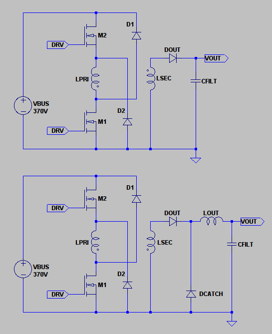
Main Line frequency is 50Hz but after ractification u r left only with DC. Now after that u have to switch the MOSFETs at high frequency ie in the range of 30 to 40 KHz. And that will be the oscillating frequency of ur transformer.
I dont have the formula for capacitor value but for a small supply (17V * 1.5Amp = 25.5W) 1uF myler is more than enough.
Now chose a frequency for ur oscillator, i suggest u 30KHz. Switch the MOSFETs at that frequency. 38 turns of primary will do and i m very hopeful that u wont require any change. but to find it experimentally place a fuse in series of the transformer winding and start with 38 turns, u must have an Ammeter on your mains supply, if the current is less than 100mA without any load on the secondary winding (Dont attach anything with the secondry winding) then u dont need any change but if the current exceeds u must increase the turns.
---------- Post added at 23:57 ---------- Previous post was at 23:42 ----------
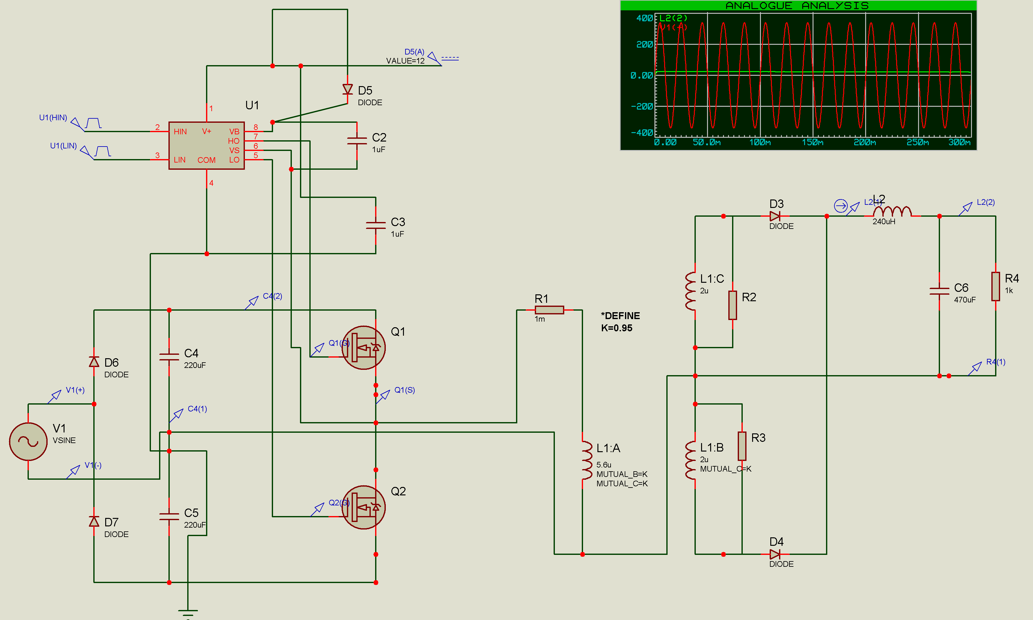
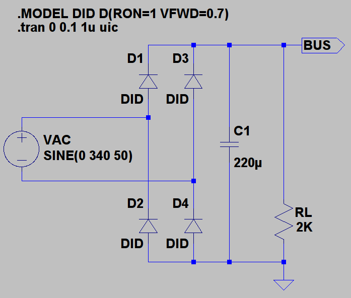
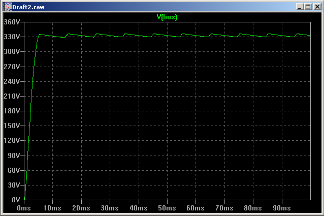
And keep in mind that this capacitor is DC blocking capacitor and have nothing to do with oscillator, as i feel from ur words that u r confusing it. the oscillation totally depends on the frequency with which u switch the MOSFETs. So u dont need any precise calculation of this capacitor. And i cant understand what u have been doing in the simulation. By the way have u decided that how u r going to drive ur MOSFETs..........
---------- Post added 12-01-11 at 00:03 ---------- Previous post was 11-01-11 at 23:57 ----------
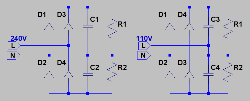
And one more thing u should keep in mind that for input 220V rms the capacitors will charge at 311V DC. But that will not be ur input voltage of transformer, the input voltage will be 311/2 =156Volts. for that 38 turns * 4 volts = 152Volts is a logical value of number of turs. Half of the voltage will drop across the DC blocking capacitor. So u must use a capacitor rating 250V DC
---------- Post added at 00:28 ---------- Previous post was at 00:03 ----------
You r still confused with winding the transformer. So follow the steps.
Decide SWG for the primary and secondry winding separately. I dont have a data book at this time with me. But just for idea, for 1.5A output 21 SWG and for input You can use 25 SWG wire. (Try doing rough winding to have a guess that u have enough space for 38 turns of primary and 20 turns of secondry. )
Now wind 19 turns of 25 SWG(say) in a layer and have both ends soldered on two different pins, note the position of start of winding say "a" and end of winding say "b".
Now give an insulation of electrical tape or kepton tape (if available, or simple electrical tape will do),
Then wind 10 turns of 21 SWG (say) in a layer and have both ends soldered on two more pins, say "c" and "d", Then wind 10 more turns of 21 SWG and sold on pins say "e" and "f" now connect "d" with "e" (end of first with start of second) this gives u center tape of secondary and "c" and "f" as two exterior ends.
Give insulation again and wind 19 more turns of 25 SWG and sold them on "g" and "h", connect "b" with "g" (u dont need this connection out), and use "a" and "h" as the two ends of primary.
Hope u got it now. And if u r confused with winding the primary in two parts, just wind 38 turns of 25 SWG in a Go and use the ends for connections..............
Main Line frequency is 50Hz but after ractification u r left only with DC. Now after that u have to switch the MOSFETs at high frequency ie in the range of 30 to 40 KHz. And that will be the oscillating frequency of ur transformer.
I dont have the formula for capacitor value but for a small supply (17V * 1.5Amp = 25.5W) 1uF myler is more than enough.
Now chose a frequency for ur oscillator, i suggest u 30KHz. Switch the MOSFETs at that frequency. 38 turns of primary will do and i m very hopeful that u wont require any change. but to find it experimentally place a fuse in series of the transformer winding and start with 38 turns, u must have an Ammeter on your mains supply, if the current is less than 100mA without any load on the secondary winding (Dont attach anything with the secondry winding) then u dont need any change but if the current exceeds u must increase the turns.
---------- Post added at 23:57 ---------- Previous post was at 23:42 ----------
And keep in mind that this capacitor is DC blocking capacitor and have nothing to do with oscillator, as i feel from ur words that u r confusing it. the oscillation totally depends on the frequency with which u switch the MOSFETs. So u dont need any precise calculation of this capacitor. And i cant understand what u have been doing in the simulation. By the way have u decided that how u r going to drive ur MOSFETs..........
---------- Post added 12-01-11 at 00:03 ---------- Previous post was 11-01-11 at 23:57 ----------
And one more thing u should keep in mind that for input 220V rms the capacitors will charge at 311V DC. But that will not be ur input voltage of transformer, the input voltage will be 311/2 =156Volts. for that 38 turns * 4 volts = 152Volts is a logical value of number of turs. Half of the voltage will drop across the DC blocking capacitor. So u must use a capacitor rating 250V DC
---------- Post added at 00:28 ---------- Previous post was at 00:03 ----------
You r still confused with winding the transformer. So follow the steps.
Decide SWG for the primary and secondry winding separately. I dont have a data book at this time with me. But just for idea, for 1.5A output 21 SWG and for input You can use 25 SWG wire. (Try doing rough winding to have a guess that u have enough space for 38 turns of primary and 20 turns of secondry. )
Now wind 19 turns of 25 SWG(say) in a layer and have both ends soldered on two different pins, note the position of start of winding say "a" and end of winding say "b".
Now give an insulation of electrical tape or kepton tape (if available, or simple electrical tape will do),
Then wind 10 turns of 21 SWG (say) in a layer and have both ends soldered on two more pins, say "c" and "d", Then wind 10 more turns of 21 SWG and sold on pins say "e" and "f" now connect "d" with "e" (end of first with start of second) this gives u center tape of secondary and "c" and "f" as two exterior ends.
Give insulation again and wind 19 more turns of 25 SWG and sold them on "g" and "h", connect "b" with "g" (u dont need this connection out), and use "a" and "h" as the two ends of primary.
Hope u got it now. And if u r confused with winding the primary in two parts, just wind 38 turns of 25 SWG in a Go and use the ends for connections..............