Continue to Site

Welcome to EDAboard.com

Welcome to our site! EDAboard.com is an international Electronics Discussion Forum focused on EDA software, circuits, schematics, books, theory, papers, asic, pld, 8051, DSP, Network, RF, Analog Design, PCB, Service Manuals... and a whole lot more! To participate you need to register. Registration is free. Click here to register now.

Scale down output voltage to feed into the ADC of the micrcontroller??

Status
Not open for further replies.

JazzRei

Member level 1
Joined
Oct 13, 2010
Messages
33
Helped
0
Reputation
0
Reaction score
0
Trophy points
1,286
Activity points
1,499
Hi...

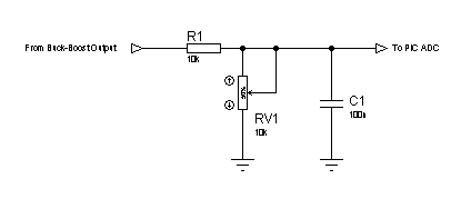
I am designing a non-inverting buck boost converter with input of 5V and produce output range of 1V to 12V but i need to feedback into ADC of the microcontroller to display the output voltage on the PC. However, I know I need to use voltage divider circuit to scale down the output voltage. Eg 12V to 3V and fed into the ADC.
Can anyone give me an idea on how I should do?

Thanks.
 

Hi,
Here's how you should do it:
87_1294339595.png


The schematic should be easy enough so that you can understand how it works. For more reading on voltage dividers read here:
Voltage divider - Wikipedia, the free encyclopedia

Before connecting the output of this circuit to the PIC, adjust the pot, so that you get a 3v output for 12v input. You can use a fixed resistor as well, but I've shown a pot so that, you can adjust the ratio and compensate for resistor tolerance/inaccuracy. You could add a zener at the output stage (5.1v) if you feel necessary in case of high voltage spikes at the input, but I think there's no need as your converter should function to produce a proper output.

Hope this helps.
Tahmid.
 

If you want more stability use another resistor from the pot to gnd, and the pot should be 1K, and center the middle value to 3V,this way the pot will adjust a smaller range but with higher resolution, and its tolerance and temp. coef. will have a smaller impact, (i would use fixed resistors, and add zener/suppressor to clip the spikes)
 

Hi...
Thanks for the reply. Btw, from the schematic, y is there a need to use capacitor?
How do I choose e capacitor value?
Wat u mean by the pot?
 

Hi...
Thanks for the reply. Btw, from the schematic, y is there a need to use capacitor?
How do I choose e capacitor value?
Wat u mean by the pot?

It's generally a good idea to put a decoupling capacitor on any line that is carrying a signal, it will help keep any unwanted signals from getting onto the line and messing the values read by your microcontroller. This way you will read a stable value into the microontroller, rather than a DC voltage with some unknown AC signal riding on top, causing ripple and inconsistent measurements. If the signal is going to be pretty much a stable DC value, try a 0.1 uF cap to start off.

A pot is short for potentiometer, a three terminal device that acts as a variable resistance. Potentiometer - Wikipedia, the free encyclopedia
 

Hi,
A pot is a variable resistor whose resistance you can vary. See the volume control in your computer sound system? When you turn it up or down, you're changing the resistance of the pot. You're adjusting the pot to vary the resistance. Of course, here you could use smaller on-board pots, which you vary the resistance by using screwdrivers. Check the above link for understanding pots.
The purpose and value of the capacitor have been stated by enjunear. It was mentioned in the diagram as "100n" which is 0.1uF, however, I guess the "n" in 100n wasn't very clear.

Hope this helps.
Tahmid.
 

Hi,

So u mean using a variable resistor and the measurement of the voltage across this variable resistor will scale down the output voltage and then feed into the ADC of the PIC?
With this formula: RV1/(RV1+R1)x output
 

Yes,
The formula is: Vout = (Vin * RV1)/(RV1 + R1)

So, the rearrangement is, Vin = [Vout * (RV1 + R1)] / RV1

Hope this helps.
Tahmid.
 

Thanks.. Tahmid.. U have given me alot of advice. Btw, what type of pot do i look into? Cos i need to design portable device...
 

My advice is to use fixed resistors, calculate the value and your done, if you have board space put 2 in parallel to have adjustment possibility.
 

My advice is to use fixed resistors, calculate the value and your done, if you have board space put 2 in parallel to have adjustment possibility.

I agree with this method. Breadboard the circuit and use a potentiometer to determine the voltage divider ratio you need. Then, disconnect the pot and measure the resistances from each leg to the wiper (center pin), and find standard resistor values that will get you close.

Since you are (basically) doing edge-detect, you don't really care about measuring the amplitude with great fidelity, so picking resistors to exactly match the pot is probably not critical to the functionality.

You can probably go down to 0402 SMT resistors, if you adjust your R values for minimal power dissipation.
 

Hi,

The voltage divider ratio can be calculated. If I am using 10K as R1 and 2.1K instead of potentiometer. Will it b fine as well?
 

Hi,

The voltage divider ratio can be calculated. If I am using 10K as R1 and 2.1K instead of potentiometer. Will it b fine as well?

That is a simple voltage divider. The result would be:
Vout = Vin * R2 / (R1+R2), or Vout = 12 * 2.1 / (10+2.1) = 2.08 V.
voltage-divider.gif


Tahmid's original circuit gives you 10k of series impedance, so you protect the sensitive A/D converter from any potentially large currents. This provides a lot of isolation, which is good design practice. If I were you, I'd keep the 10K where it is, and replace the pot with two divider resistors (which is what the pot would act like, except variable and quick to expirement with). Make sure the divider resistors are much lower in value than 10K, otherwise your divider will include a lot of voltage drop from the 10K. Somthing like a 348 and 1000 ohm divider, or a 348 in parallel with a 7.5k, then the 1k. That'd give you R2 = 1/348 + 1/7500 = 332.57 and R1 = 1000, so R2/(R1+R2) = 0.25. So 12V * 0.25 = 3V.
 
Dear Sir,

You have all the data you need, its a very simple, if not the simplest possible schematic... if you aren't confident build just download some free circuit simulator :)
 

Dear Sir,

You have all the data you need, its a very simple, if not the simplest possible schematic... if you aren't confident build just download some free circuit simulator :)

and/or review how to use Ohms law (V=I*R) to calculate values in simple circuits.
 

Thanks everyone for ur reply. U guys have provided me with great help.
 

Status
Not open for further replies.

Part and Inventory Search

Welcome to EDABoard.com

Sponsor

Back
Top