Continue to Site

Welcome to EDAboard.com

Welcome to our site! EDAboard.com is an international Electronics Discussion Forum focused on EDA software, circuits, schematics, books, theory, papers, asic, pld, 8051, DSP, Network, RF, Analog Design, PCB, Service Manuals... and a whole lot more! To participate you need to register. Registration is free. Click here to register now.

89S51, 89S52 ISP Programmer using serial port or USB

Status
Not open for further replies.
i have connected max232 like this here is the file
 

Attachments

  • RS232C Level Converter.rar
    9.9 KB · Views: 220

Sir, I went that shop, from where i bought that blank At89c2051 there is no programming device they had. In that case what should i do? I'm using a USB to comport cable it is usable to program? i've given the link below
 

here is some picture of my schematics...
 

Attachments

  • DSC02497.JPG
    DSC02497.JPG
    212 KB · Views: 159
  • DSC02505.JPG
    DSC02505.JPG
    328.7 KB · Views: 144

Hello everyone,
There are always many posts here asking about ISP programmers for the atmel 89S51 or 89S52 mcu's. Most commonly available are the FREE programmers that use the parallel port of your PC.

These programmers are not reliable, or do not work consistently on some parallel ports. If you happened to get stuck with a motherboard on your PC like mine, you would be lucky to get the programmer to read the signature bytes especially with windows XP or higher. These days computers are no longer equipped with a parallel port. I have been using this programmer for a few years now reliably even with a USB to serial adapter cable.

I use the 89S series mcu's quite a bit because they are inexpensive and easy to program (no fuses, or other problems). I wanted an easy to use programmer that would allow me to program the 89S mcu's in circuit without removing it every time.

I did not want to go through all the trouble to write a windows application, so I thought I would just use an existing one and modify the code in the programmer to do ISP operations instead of high voltage parallel programming as in the 89S51/89C52. I chose this one:

**broken link removed**
The ezdl4.exe has nothing to do with me and does not need to be changed to work with this programmer.

The circuit I chose was the same circuit as an avr910 programmer except that an 8051 device is used for the programmer. (the reset circuit will be different and the crystal will be 11.0592MHz) I chose this because I already have an avr910 programmer board therfore I would not have to go through the trouble of making another board.

Have a look at the schematic below. You can use any 8051 mcu for the programmer as long as you adhere to the pinout, and it must hold at least 4K in size. The circuit can take power from your target, or supply power to the target, if the power from the programmer (as with the avr910 programmer) is connected to your target circuit.

Now the only problem is: Somehow you have to get the code into an 8051 MCU. If you do not have a programmer, this will be a problem. Once that is done you will have a very reliable programmer.

Everything is included in the zip file. Please read the readme.txt for instructions.
Any suggestions are welcome. Please post them here.

ctownsend

whether the programmer that you can give to AT89S2051?
I've tried like you tp programmers sometimes have never been able to that is in the process verivy unsuccessful.
if I use my ISP's port AEC pararrel always successful although a few times usage
 
hi ctownsend
good job u work on it
its looking like this programmer but software is changed
**broken link removed**
 

bring the code to the shop and ask the person to program it for you. Lots of shops will do this free or for almost no cost to you.

---------- Post added at 16:36 ---------- Previous post was at 16:25 ----------


Corrections to the above post (don't know why I can't edit my own post??)

typos HERE:
I did not want to go through all the trouble to write a windows application, so I thought I would just use an existing one and modify the code in the programmer to do ISP operations instead of high voltage parallel programming as in the 89C51/89C52.

AND HERE:
Have a look at the schematic below. You can use any 8051 mcu for the programmer as long as you adhere to the pinout, and it must be at least 2K in size. The circuit can take power from your target, or supply power to the target, if the power from the programmer (as with the avr910 programmer) is connected to your target circuit.

The original post showed 4K size (that was the original code before the final release)

---------- Post added at 16:44 ---------- Previous post was at 16:36 ----------


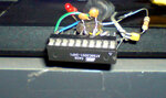
help us help you. Show us a schematic of what you've done. what chip are you using for the programmer? what are the capacitors used for the clock circuit? What are the capacitors used for the MAX232 circuit? Are you using a genuine max232?

What does your reset circuit on the microcontroller look like? Did you connect EA to VCC? Are you taking power from the target or supplying power to the target? What voltage?

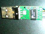
answer every single question and post a picture of what you've done. this is the only way I or anyone else can offer help to you. The code and circuit does work. I used it for more than 2 years now.

i am also facing same problem as hansika here
here is my schematic
 

Attachments

  • schem.bmp
    576.1 KB · Views: 213

did you see RS232C Level Converter like i have posted above should work ? i have completed this project in one shot with no problem your problem is in wiring you must check wiring first pls check wiring
this is my version
there is no connection to rest you are not following minimum circuit for 89c2051 ?that may be the cause .
 
Last edited:

i am using AT89S51 controller for that same circuit and software but the program is not downloading ........
what is the problem
u had seen that circuit, but the programmer is always saying that "trying to connect COM1" why this is happening i have dumped the given hex file in the AT89S51 controller.
 

are you using serial port or usb to serial port
i am using this programmer since few months and i am using only serial port and window xp 2003
 

Here is an updated schematic. I tried to make it a clear as possible.

You DON'T need the LED's. If there is a problem, you will never know if the led's are NOT installed.

The led's indicate the following:
Green LED: This led goes on when a successful connection to the target has been made.
(i.e. the target successfully entered ISP or programming mode) If it fails, or a device not connected
the RED LED will be lit.

Yellow LED: Indicates the programmer is busy. It will come on when the programmer is reading or writing to the target chip.

Red LED: Comes on when there is an error, whether it is writing, reading, entering programming mode, etc.

The best way to start the programmer is to have the programmer connected to the target circuit. Ensure that everything is working, then start the PC program.

If using a 20 pin device (i.e. 89C2051) for the programmer just follow the same pinout using pin names. (P1.1, P3.0, P3.1, XTAL1, XTAL2, etc..)

This schematic shows the programmer taking power from the target. You can eliminate this and just connect to a 5V power supply.

Some troubleshooting tips:
If you are using a USB to RS232 converter, PLEASE use a good one (not one from China or from ebay!!) Most of these don't work. Sometimes windows will install your com port on a higher number than the EZDL4.exe will search for. I have seen the programmer not being detected when the com port is com10 or higher. Check your com port in the device manager. If this is the case, you can change the com port to a different port if one is available.

If you are having trouble with your USB to RS232 converter, wire the TXD to RXD on the USB to RS232 converter and type some chars in hyperterminal at various baud rates. You can also check this on the TTL side of the max232 on your programmer board.

With the microcontroller removed from your programmer, join TXD and RXD on the microcontroller socket. Ensure your max232 is being powered by 5V. Now try typing some chars at various baud rates with hyperterminal. If you see the chars in the terminal, the serial portion of the circuit is working. (although some cheap USB to RS232 converters work sometimes, and are not reliable) You can do the above test with a regular serial port as well.

 
Last edited:

I am facing almost the same problem. I am using the serial port (COM-1) directly from my desktop PC with Windows XP. This COM-1 port has been tested as working with many other applications.

While the power is ON, no LED glows.
When I start EZDL4.exe in computer by double clicking the icon, the green LED glows. But the alert message “Try to connected by : COM1” blinks on programme window and no buttons activate for further action.

What may be the problem? As the green LED glows when the software starts, we may assume that serial port able to communicate with the master processor (AT 89s52 in this case, programmed by other conventional programmer). Then why the software gives warning message?
 

As the green LED glows when the software starts, we may assume that serial port able to communicate with the master processor (AT 89s52 in this case, programmed by other conventional programmer).

the green LED has nothing to do with serial communication. (read my post above & follow the circuit). Double check the capacitor installation for the MAX232. Some of the "+" and "-" can be misleading. If your circuit matches the schematic above, it will work.

here is a small hex file to test the programmer hardware & serial communication. If you are having trouble, PLEASE READ ALL OF THESE these instructions!

1. Program this code into the microcontroller you are using for the programmer. This code works for 20 pin devices and 40 pin devices as mentioned above.

2. In hyperterminal or any terminal using 9600 as the baud rate, type a char in the terminal window. If the serial communications are working on your board, the char you typed will echo back to the screen. If the char does not echo back to you, you need to check your circuit!!

3. Each time you type a char, the next led will light up.
Led's will go on in the following order:1. Green, 2. Yellow, 3. Red.

Code:
:03000000020030CB
:1000300074FFF590F5B0759850758DFD758920D2D7
:100040008E12005512004D12005D80F522F5993098
:1000500099FDC299223098FDC298E5992220910716
:100060007590FFC29280162092077590FFC2938010
:0E0070000C2093077590FFC2918002C291226E
:00000001FF
I don't know what else to do to make it more clear. The circuit works really well!
 
Last edited:

YES you can! read the readme that comes with the programmer.
2. The lock function works, however all lock bits will be programmed.
The EZDL4.exe program will display the message "Lock failed!".

The reason for this is because the EZDL4.exe program tries to read the flash after
the lock bits have been programmed. In the 89C devices, the flash will read FFh
if the device is locked.

With the 89S devices, the flash will read 00h 01h 02h 03h 04h 05h..etc.
which is not FFh, therefore the EZDL4.exe program indicates failure programming
lock bits.

You can verify that the device is locked by reading the flash to a file.
Open the file, and verify that the flash contents are 01 02 03 04.

There are a some commands that were disabled from the original 89C version.
Working commands are read, write, lock, verify and fast verify.
 

program the chip with code you know. Lock the chip. Now read the chip. Post the code here. I will bet you that the code is 00010203040506.......

compare the two files. they won't be the same. EVEN THOUGH THE EZDL4.exe program gives a message "lock failed" it still works. The atmel code in the programmer takes care of locking the device. It is very reliable and works well.
 
Status
Not open for further replies.

Similar threads

Part and Inventory Search

Welcome to EDABoard.com

Sponsor

Back
Top