Continue to Site

Welcome to EDAboard.com

Welcome to our site! EDAboard.com is an international Electronics Discussion Forum focused on EDA software, circuits, schematics, books, theory, papers, asic, pld, 8051, DSP, Network, RF, Analog Design, PCB, Service Manuals... and a whole lot more! To participate you need to register. Registration is free. Click here to register now.

[SOLVED] Replacing 5 to 32 line decoder with four 3 to 8 line decoder???

Status
Not open for further replies.

moonnightingale

Full Member level 6
Joined
Sep 17, 2009
Messages
362
Helped
5
Reputation
10
Reaction score
5
Trophy points
1,298
Activity points
3,832
I am atatching the Pic.
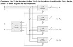
Kindly tell me when we are having 5 to 32 decoder, we are having all 32 outputs as unique outputs
but when we are using 3 to 8 decoders, the outputs are not unique. from figure u can see that D0 and D8 will be same
similarly D15 and D23 will be same. Each output is repeated four times.
So how can we use it practically.
 

Attachments

  • Q3.jpg
    Q3.jpg
    61.6 KB · Views: 176

Each 3 to 8 decoder outputs are not unique, however the E input to the 3 to 8 decoder means that only one decoder is enabled (active) at any one time. There is no case when more than one 3 to 8 decoder is active. Thus signals A4 and A5 determine which 3 to 8 decoder is active correctly decoding the 32 lines.
 

Yes exactly that i know that output of 2 to 4 decoder acts as enable.
I just want to ask that in practical world can we replace 5 to 32 decoder with 3 to 8 as u also mentioned, its outputs are not unique.
So practically i think it has no use for implementation.
 

Your input is 5 bits from 00000 to 11111 which is equal to decimal value 0-31 (32 different values), so when you have a 5 bit line decoder the result will be 32 different output lines.

In your schematic consider it like a number from 0 to 7 (A0,A1,A2) and 2 more bits (A3,A4) as carry

when A4=0 and A3=0 output is (0*8) + (A2,A1,A0)
when A4=0 and A3=1 output is (1*8) + (A2,A1,A0)
when A4=1 and A3=0 output is (2*8) + (A2,A1,A0)
when A4=1 and A3=1 output is (3*8) + (A2,A1,A0)

Alex
 
The one is as practical in the real world as the other. All we are talking about is signal flow. Whether we are talking 5-to-32 or 3-to-8, each path IS UNIQUE. Try simulating the circuits: **broken link removed**.
 

Your input is 5 bits from 00000 to 11111 which is equal to decimal value 0-31 (32 different values), so when you have a 5 bit line decoder the result will be 32 different output lines.

In your schematic consider it like a number from 0 to 7 (A0,A1,A2) and 2 more bits (A3,A4) as carry

when A4=0 and A3=0 output is (0*8) + (A2,A1,A0)
when A4=0 and A3=1 output is (1*8) + (A2,A1,A0)
when A4=1 and A3=0 output is (2*8) + (A2,A1,A0)
when A4=1 and A3=1 output is (3*8) + (A2,A1,A0)

Alex

Thanks alexan
ur explanation is really very good andnowi have understood
 

Status
Not open for further replies.

Part and Inventory Search

Welcome to EDABoard.com

Sponsor

Back
Top