Continue to Site

Welcome to EDAboard.com

Welcome to our site! EDAboard.com is an international Electronics Discussion Forum focused on EDA software, circuits, schematics, books, theory, papers, asic, pld, 8051, DSP, Network, RF, Analog Design, PCB, Service Manuals... and a whole lot more! To participate you need to register. Registration is free. Click here to register now.

Why the X band LNA freq shifts?

Status
Not open for further replies.

tony_lth

Advanced Member level 5
Joined
Jul 28, 2010
Messages
2,088
Helped
377
Reputation
756
Reaction score
368
Trophy points
1,363
Location
Beijing
Activity points
12,641
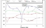
I designed a X band LNA with FHX13LG from Eudyna. I had already simulated with S-parameters and noise parameters both in ADS and AWR, but I didn't do the momentum simulation. The simulation result is fine, 13dB gain in 9.1G~9.7G and noise figure is about 1.1dB. I designed with Rogers RO4350B 10mil 1/2oz substrate, and all the match stubs is microstrip line, no lumped element except the DC block RF capapcitors.
But when I tested the PCB board, the S11=-0.6dB, and S21=-7.8dB at 9.5GHz. And at 6.5GHz, the S11=-18dB. It seems that the pass band shifted down from 9.5GHz to 6.5GHz.
I want to know:
1. What cause freq shift down?
2. Should I do paste and try to adjust the pass band to 9.5G? I had tried to do so, and I found it's easier to make S21=10.5dB/NF=3.5dB at 6.5G. My objective is NF(max)=1.5dB/S21>10dB at 9.5GHz, I had tried paste 1 hour and the best result is S21=0dB. I will paste carefully later.
3. Should I do the momentum simualtion to verify the result? I am a newbie for momentum.
4. Is it because the discrete of the components from the typical S-paras?
Thanks.
 

From 9.5GHz to 6.5GHz is a lot, and I don't think is about Er change of the material (this change can shift the frequency).
At 9.5GHz parasitics of components are very important, and also their placement on the PCB. Ideally would be to have the S-parameters of each lumped component used, but sometimes is hard to get them up to this frequency.
Momentum is a good option, especially for simulating the influence of the parasitics of pads and vias.
 
I design wideband amplifier between 30MHz-1500MHz and I do MoM simulation for those frequencies and I find some serious differents between simulation results and measurements at most of the time.
You have to do MoM simulation at those frequecies, it's very obvious. Use Microwave mode and increase mesh density as much as possible. For this simulation, I suggest you to use 64bits computer to benefit from its memory adressing capability.The MoM simulations will take so long time ( for instance my last simulation of a demo board took 6 days with 64bits machine) but it will give you quite close results.
For PCB-board application, I recommend Sonnet. ADS is also not too bad but Sonnet is more accurate in these applications.
Avoid using discrete components such as low cost capacitors, multilayer inductors. they will fail at those frequencies. Instead, use single layer high quality capacitors-for instance from Johansson or ATC- for Microwave applications.
Temperature and environement humidity are also important.Measurement accuracy depends on may factors such as calibartion,temperature,humidity,cable quality,connector quality,assembly quality etc..
Involving into design at 9-10 GHz is quite difficult.
 
Thanks, in the input port I used an isolator, whose pads is 2mm(L)X1.5mm(W), but my 50R trans line is 0.5mm wide, so I guess this will cause trouble. And the dc block capacitor is 0402 package, Murata microwave capacitor, I tested its insertion loss is about 0.1dB.
I will use 64bits ADS to simulate the PCB, bceause I am a newbie on momentum, how to build model for FHX13LG and capacitor in ADS? do you have any training file, tutorials, examples for momentum? does it have any way to directly import Altium PCB into momentum?
thanks.
First, you should simulate your board with success and then you create a layout like component from this board to be able to simulate in schematic environment.In this schematic window, the layout will be transferred with its' ports. After that, you connect your component ( linear and nonlinear) to these ports and you can do lnear and nonlinear simulation in schematic.
For small signal simulations, s-parameters are sufficient of each component.S-parameters should normally be available this pHEMT on their website.For other components, you should use respective s-parameters defining in black boxes in ADS.( Data Items)

You can also transfer your PCB layout into ADS by using Gerber output of the PCB. Then don't forget to use "merge union" function of ADS because Gerber outputs have generally many d-codes
and they may create meshing complexity in ADS that is unwanted.
For more information, search internet, you can find some valuable documents about this..
 
Why not start from the beginning in debug this application?

If your design have been designed properly and no BIG layout mistakes have been done, I do not expect this very bad results.

First point to check: DC bias is as you expect? S parameters you have used in the simulator are valid only for the specified bias conditions. Did you check bias point carefully?

I hope it can help.

Mazz
 
The S-paras of FHX13LG is based on Id=10mA/Vd=2V, my bias is Id=12mA/Vd=1.9V, initially I guessed the bias is OK. Do you think so?
 

I simply simulated in AWR with schematically adding the isolator PADs, and capacitor pads, the result is very similiar to the true value that I had tested. So the PADs impact is very large. I will do the momentum simulation for more accurate result. Thank all of you.
 

Attachments

  • Debug_V1.jpg
    Debug_V1.jpg
    98.8 KB · Views: 119

Status
Not open for further replies.

Part and Inventory Search

Welcome to EDABoard.com

Sponsor

Back
Top