FMradio
Member level 3
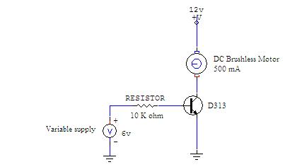
will it work ??
Guys i want to vary the speed of a DC 500mA motor, now tell me am i right ??
am i doing in the right way if not then tell me what the proper way to do so please . . .

Guys i want to vary the speed of a DC 500mA motor, now tell me am i right ??
am i doing in the right way if not then tell me what the proper way to do so please . . .