Continue to Site

Welcome to EDAboard.com

Welcome to our site! EDAboard.com is an international Electronics Discussion Forum focused on EDA software, circuits, schematics, books, theory, papers, asic, pld, 8051, DSP, Network, RF, Analog Design, PCB, Service Manuals... and a whole lot more! To participate you need to register. Registration is free. Click here to register now.

flyback transformer noise

Status
Not open for further replies.
Dear FvM please help me if you have a little time.
 

I test 3842 in non-feedback state and pwm was constant
Is this also true for output volatge/load conditions that caused instable behaviour with feedback. It's possibly not easy to vary the
control input in this mode, but it should be possible. If you can achieve stable operation this way, you basically proved the current
mode operation itself is stable. Then you can try to operate the feedback with PI compensation (C7 with a series resistance). C7
can be 100 nF or even larger, the series resistance should be in the low kohm range.

P.S.: I took a closer look at the circuit and found two points:

- With full load, the circuit is not operating in discontinuous mode. So slope compensation is needed for stable operation.

- The transformer windings ratio is unusually high for a flyback converter. Even at highest output voltage, the flyback voltage is still lower than the forward voltage. I guess, the dimensioning has been choosen due to the low voltage rating of the switch transistor.
 

    tictac

    Points: 2
    Helpful Answer Positive Rating
Hi FvM,thanks you for consideration

Is this also true for output volatge/load conditions that caused instable behaviour with feedback
yes, output has instable behavior when we have sound.

With full load, the circuit is not operating in discontinuous mode. So slope compensation is needed for stable operation.

I test it with 37K load at output. but the current of source was discontinuous(perhaps) .it is the source pin of mosfet with 37k load and 1060 volt.in this voltage it doesnt have sound. and with this load(37K) the output voltage doesnt reach to 1250 volt. :cry:


its new schematic that I was remove snubber circuit that in parallel with mosfet and replace 3842 with 3844 and adjust RC of oscillator for 50 khz.


and its the drain waveform.


but I dont konw why it is like a sinus wave!!!?? can you guess from the picture that it work in DCM or CCM?


The transformer windings ratio is unusually high for a flyback converter. Even at highest output voltage, the flyback voltage is still lower than the forward voltage
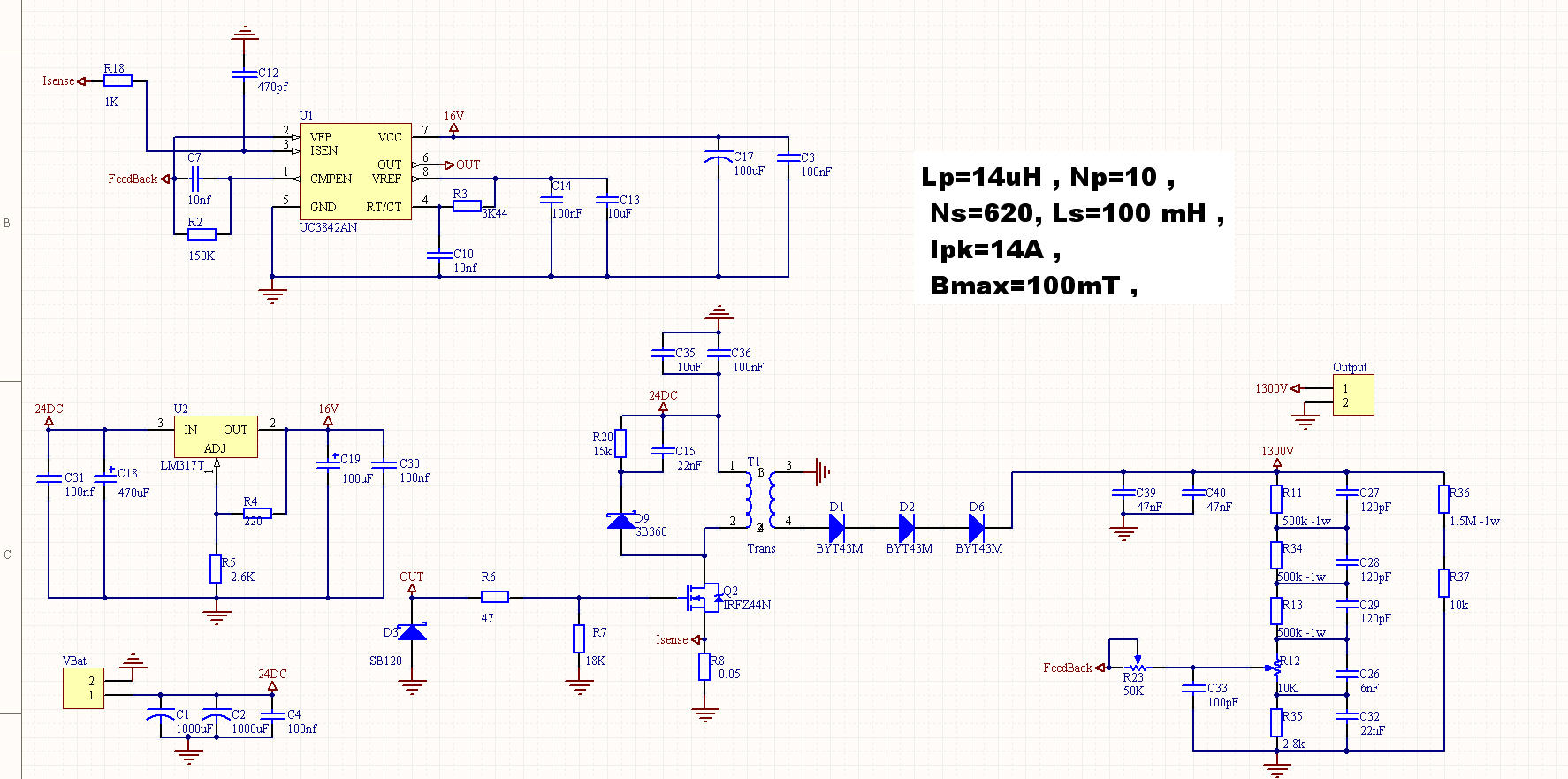
I guess that 620 rounds for secondary is high.I calculate that Ls=85mh but for considering dissipation I take it 100mh!!! is it false?

regards[/quote]
 

can you guess from the picture that it work in DCM or CCM
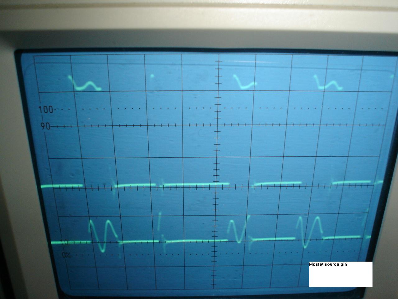
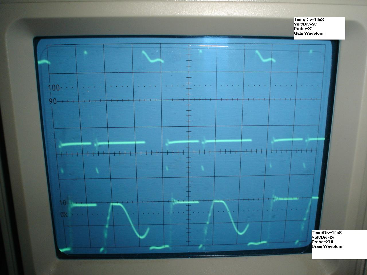
The "sine wave" following a rather short on-period is surely DCM, the other cycle looks rather like CCM. So I guess, it can be still a problem of basic current mode instability with missing slope compensation.

Dis you ever try to add a slope compensation circuit as suggested in UC3842 datasheet?
 

    tictac

    Points: 2
    Helpful Answer Positive Rating
is it enough to connect pin 4 with one 50k multiturn to pin3?

regards
 

Basically yes, depending on the resistance level, a NPN transistor is used to reduce the load to the RC oszillator. I once apllied the
technique in a design prototype and it basically worked, but I don't remember the details.
 

    tictac

    Points: 2
    Helpful Answer Positive Rating
I connect pin3 and pin4 with one multiturn 50k and it didnt any change. I have sound. is there any reference for designing slope compensation?
 

May be you proved, that the problem can't be handled by slope compensation.
 

    tictac

    Points: 2
    Helpful Answer Positive Rating
No. I mean that I can not silence the sound. I braze one multiturn to pin4 and pin3 . but it didnt silence. Maybe it needs transistor.

Added after 2 hours 31 minutes:

Now, I test it with bc550 and one multiturn(50K) . it decreases the sound a little. I ask for my problem from some proffessional ,and they tell me that you must use half bridge or full bridge . flyback doesnt proper for a wide range of voltage. but I want to work on this circuit and I have no enough time to change my topology. Can I get good stability in all range of voltage?I want 35mA in all range of voltage and I want constant output voltage (maximum 20 volt change) by changing the load in all range of output voltage. is it reachable with flyback?

regards
 

Hi
If we ignore the presence of noise, I now have a new problem. I put 35K load at output. I use 3844. but I cant get 1250 volt with this load and output voltage was 800 volt. how Can I change transformer for getting 50 watt at output??(its now about 20 watt)

its my core details. EE50-40
Lp=14 uH
Ls=97mH
Ipk=14A
Bmax=100mT
f=50khz
Np=10,Ns=620
Lg=0.07mm
effective core lenght=93mm
effective core cross section=256 mm^2


https://www.4shared.com/file/258378028/4cf1a474/core.html

regards
 

I dodn't see, that the insufficient power output can be explained from the given transformer parameters as such. It seems
to be rather a problem of extensive losses. What's the input power to the converter with 20 W output?

A different transformer dimensioning can reduce the peak current for a specific transmitted power. But it's possibly conflicting
with other parameters, e.g. power switch maximum Vds, core size.
 

    tictac

    Points: 2
    Helpful Answer Positive Rating
Hi
the input voltage is 20v to 28 volt (Imax=10 A)


A different transformer dimensioning can reduce the peak current for a specific transmitted power.
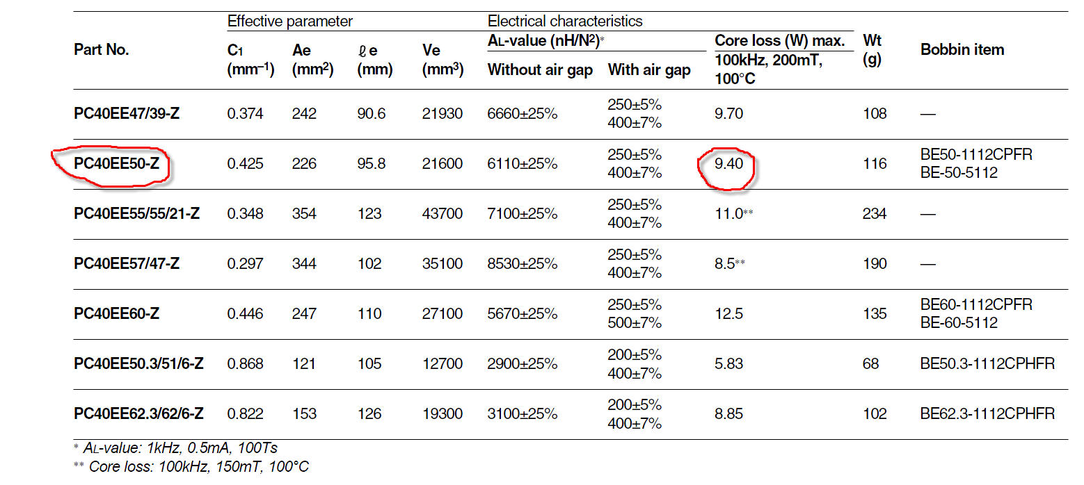
is it core with the smaller cross section? I get the core cross from relations. I think it is not more effective. can you give me the way to get the better core with minimum losses ?

regards
 

I'm rather interested to know the average input power, in other words the efficiency.

To increase the efficiency, I would try to change the operation to continuous mode with reduced current ripple, which involves a
higher primary inductance. But I won't change anything before knowing about the actual effciency and major loss contributions.
 

    tictac

    Points: 2
    Helpful Answer Positive Rating
Pout=1300 * 0.04 =52 watt

Pin=Pout/eff=52 / 0.75 = 70 watt (I)

Ipk=5.5*Pout/Vin(min)=14.3 A

Fs=50 khz , Ton=10 us- 1 us=9 us. (its because of UC3844.)

Lpri=Vin(min)Ton/Ipk=12.5 uH

Pout(est)=F*Lpri(Ipk)^2/2=64 watt (II)

(II) <(I) so I cant get 52 watt at output.
If I take Ton=10 uS, so Pout(est) can be equal to 70 watt.

if I take Fs=20 khz, so I can get 70 watt power so 52 watt output power. is it true?

but there is another important problem as you say and it is losses.
what Can I do for this?
the mosfet get very hot.so hot!!!

I now apply Vin=26v and the current is I=1.6A --->Pin=41.6 watt

and Vout(max)=814v , Iout=23 mA --->Pout=18.7 watt

the efficiency is about 44%

is it clear? May be I cant understand your purpose. please ask me anything if you want to understand.

regards.
 

Hi
I change my oscillator capacitor with 4.7 nF and use one multi turn(10K) for its resistor. I adjust it to 50 khz. now duty cycle goes up to 50% and output voltage goes up to 1000 volt with 35k load. now the efficiency is 60%. how can I do it better?( for example 1250volt with 32K load) . one of my friend told me that use mosfet driver inside of 3844. can you tell me your idea about it?

regards
 

I don't think, that the losses are primarly caused by the gate drive, but you are slowing down the switch operation with the
47 ohm gate resistor. Reducing this resistor would be first measure to improve the gate drive and speed up switching.

I rather think, that most losses are created by avalanche breakdown of the IRF44.

Generally, your measurements show, that the power and efficiency calculations are rather theoretical.
 

    tictac

    Points: 2
    Helpful Answer Positive Rating
the gate resistor is 22 ohm.

Generally, your measurements show, that the power and efficiency calculations are rather theoretical.

I measure parameters with volt meter and amp meter. can you describe it more?
 

Hi
now I replace the 60v schottky diode with 100v diode and 10nf capacitor with 4.7k and it works. the spike voltage of drain was 60 volt but before it rises to 75 volt.
but one question
the maximum output voltage is 1300 volt(Iout-max=40 mA). I use 3 very fast diode (BYT43M , 1000v) with two capacitor(47 nF , 1600V)
is it a correct rectifier or I must use one very fast diode with 4000 reverse voltage?
also I want to put 3 resistor in parallel with 3 output diode. how can I calculate the value of these?


regards

Added after 37 minutes:


I use EE50/40. I want 50 watt at output. but now about 30 watt. at above datasheet says that about core losses( 9 watt). does it means that I should suppose output power at about 60 watt?
 

Serious connection of multiple diodes is no problem in my opinion, it should work without additional resistors.

Regarding core losses, you calculated 100 mT, versus 200 mT specifications for the losses, so you won't have more than
1.5..2W losses, which is more convenient. But in fact, you have to consider all loss contributions. Their sum is apparently causing
the efficiency problems with your design.

I measure parameters with volt meter and amp meter. can you describe it more?
I didn't doubt about the emiprical measurements, but the output power and efficiency predicted from general design
considerations, e.g. "Pin=Pout/eff=52 / 0.75 = 70 watt"
 

    tictac

    Points: 2
    Helpful Answer Positive Rating
Serious connection of multiple diodes is no problem in my opinion, it should work without additional resistors

maybe they have different reverse voltage and it cause damaging diodes.

and the maximum output voltage is 1300 volt(Iout-max=40 mA). I use 3 very fast diode (BYT43M , 1000v) with two capacitor(47 nF , 1600V)
is it a correct rectifier or I must use one very fast diode with 4000 reverse voltage?


regards
 

Status
Not open for further replies.

Similar threads

Part and Inventory Search

Welcome to EDABoard.com

Sponsor

Back
Top