Continue to Site

Welcome to EDAboard.com

Welcome to our site! EDAboard.com is an international Electronics Discussion Forum focused on EDA software, circuits, schematics, books, theory, papers, asic, pld, 8051, DSP, Network, RF, Analog Design, PCB, Service Manuals... and a whole lot more! To participate you need to register. Registration is free. Click here to register now.

non inverting amplifier lmv721

Status
Not open for further replies.

Kinshoro

Member level 3
Joined
Feb 18, 2010
Messages
60
Helped
0
Reputation
0
Reaction score
0
Trophy points
1,286
Location
Bern
Activity points
1,784
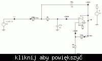
I have made a non-inverting mic preamp using this opamp... the problem is that I should have equal voltages at both the positive and negative end.... but the negative terminal is always having a variable voltage even though I have got a dc offset of 1v. It varies from 2.25v to 1v. I have attached the diagram of my circuit....
 

The typical input bias current of the LMV721 is 260nA but that is not enough to cause the problem. I just tried it with my simulator and the results don't look right. I suspect there is a fault in the Spice model. I will see if I can spot the problem, but you may want to try another opamp in the meantime or contact National Semiconductor.

Keith.

Added after 24 minutes:

I think the problem with the LMV721 model is that the node order for the subcircuit is mislabeled. This is a National Semiconductor fault, not yours! If I connect positive power to what they say is negative power, ground to what they call the output and take the output from what they label the the positive power it works correctly!

Keith.
 

    Kinshoro

    Points: 2
    Helpful Answer Positive Rating
did u simulate it???? R u sure that it is a fault of national semiconductors....???? or is it that it works well with that configuration..........
 

Yes, I have simulated it.

The fault is with the model National Semiconductors supply. They give the pin order as +in/-in/out/V+/V- but that isn't how the model is designed. I think the order should be +in/-in/V+/V-/out.

Try just about any other model (eg LMV751) and you will see it works fine.

Unfortunately errors do creep in to manufacturers models. I have tried to get them to correct faulty ones but usually I either get a disclaimer "supplied as is..." thrown back at me or some numpty who thinks SPICE means turmeric.

Keith.
 

    Kinshoro

    Points: 2
    Helpful Answer Positive Rating
thanx keith... I really appreciate ur advice.... I think I will change the opamp and see if I get a better result..... but I can use the lmv721 if I set the pins according to what u told me right??????
 

Yes, the LMV721 is fine - it is just the model that is incorrect. Just try another opamp for the simulations. I quickly tried the LMV751 which seemed fine. The original simulations I posted were with a Maxim chip because that is what I used for a similar microphone amplifier & filter. For that application I needed a high bandwidth - well above the audio range.

Keith
 

    Kinshoro

    Points: 2
    Helpful Answer Positive Rating
ok so if I use the real component of lmv721 than its fine..... thnx..... so the datasheet of lmv721 is correct... I thought when u said that the pins are not set right I thought u meant they manufactured it in the wrong way and not according to their data sheet... So it was just wrong in the simulation............
 

Correct - it is just their model that is wrong. That does make it confusing though if you want to simulate it! This is the connection I had to use:


Then you get this:


Keith.
 

    Kinshoro

    Points: 2
    Helpful Answer Positive Rating
Status
Not open for further replies.

Similar threads

Part and Inventory Search

Welcome to EDABoard.com

Sponsor

Back
Top