Continue to Site

Welcome to EDAboard.com

Welcome to our site! EDAboard.com is an international Electronics Discussion Forum focused on EDA software, circuits, schematics, books, theory, papers, asic, pld, 8051, DSP, Network, RF, Analog Design, PCB, Service Manuals... and a whole lot more! To participate you need to register. Registration is free. Click here to register now.

Question about Bandgap reference and BETA of Bipolar devices

Status
Not open for further replies.

palmeiras

Full Member level 6
Joined
Feb 22, 2010
Messages
375
Helped
61
Reputation
122
Reaction score
50
Trophy points
1,308
Location
South America
Activity points
4,199
hello everybody

Please, if somebody can help me.
I frequently read in the literature, that bipolar transistor (BJT) – usually vertical parasitic PNP devices – used in Bandgap voltage references (please, see figure 1) must have high values of BETA (common-emitter current gain).
I don’t understand why this parameter must be high. If this parameter is low, the base current will be significant. However, the base current of both Q1 and Q2 devices will be significant, and for me, this effect will not damage the temperature performance of the voltage reference.

So, what is the impact of low value of BETA on the performance of BJT?

Thank you very much,

Palmeiras
 

The base current is a source of nonideality, figures heavily
in curvature and varies strongly with temperature and so on.
High beta means lower base current.

In the transdiode the beta really cleans up the ideality
and log-linearity of the "diode", if you have enough of it.
 

Re: Question about Bandgap reference and BETA of Bipolar dev

Hi dick_freebird,

Thank your very much for your attention. Please, could you explain in another way, why the base current will generate nonideality at the output voltage?
About temperature compensation of BGRs, what matters is the summing of two voltages: the thermal voltage (PTAT) and the VBE voltage (CTAT).

for device Q1: VBE1 = VT*ln(IC/IS); => VBE1 = VT*ln(alpha*IE/IS)
for device Q2: VBE2 = VT*ln(IC/n*IS), ==> VBE2 = VT*ln(alpha*IE/n*IS)

Then cancelling alpha (aplha = BETA/(BETA+1)) of these two devices... and calculating deltaVBE, we have:

deltaVBE = VT*ln(n);

So, this make me to conclude that low-beta is not a problem. Where am Im doing a error in such analysis?

Thanks again!
 

I cannot check this at the moment, but isn't the detrimental effect of low beta that the beta depends on collector current? The multiple transistors share the same collector current as the single one hence beta will be different so base current matters.

Keith
 

Re: Question about Bandgap reference and BETA of Bipolar dev

Hi Keith,

Thanks very much for your help!

I agree with you: BETA depends on collector current. But for me, the beta_x_CollectorCurrent dependency affects both transistors (Q1 and Q2) in a similar way.
For example, consider the deltaVBE equation (described above). Even alpha (or BETA) parameter varies with temperature, both alpha (BETA) - of Q1 and Q2 - will vary equal, permitting the cancellation in the equation.

For me, since the collector current and temperature are equal for Q1 and Q2; BETA of these devices are equal.

Am I right? Why did you write that beta are different?

Thanks!!!!!
 

Re: Question about Bandgap reference and BETA of Bipolar dev

As long as the beta is high, there would be very low base current and no voltage drop on the base resistance. If the beta is low, base current and hence the drop on base spreading resistance will be significant which will affect the temperature characteristics of the diode and will show up as an error in the diode equation. Since this is error cant be matched (exponential term vs linear term) across temperature across both the arms, a low beta will be a problem.
 
Re: Question about Bandgap reference and BETA of Bipolar dev

palmeiras said:
Hi Keith,

Am I right? Why did you write that beta are different?

Thanks!!!!!

The betas will be different because the collector currents will be different. With a bandgap you normally put the same current through both "arms" - one with one transistor and the other with more )4 in your example). So, the current down the arm with 4 transistors is shared between the 4 so they each get a quarter of the collector current. Hence the beta will be different and the base current error will creep in.

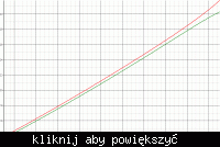
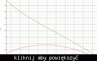
As an example this is a plot a of bipolar bandgap (I modified the values for 4 transistors as I had used 12). The red trace is the normal temperature curve with the standard BF=220 of the process. For the green plot I dropped BF to 22. You can see the effect.


I have also plotted the beta of the transistors in each arm. As you can see they are slightly different (due to the collector current difference). The same will be true of when BF=220, but the base current will be smaller therefore the effect will be smaller.


Keith.
 

    palmeiras

    Points: 2
    Helpful Answer Positive Rating
Re: Question about Bandgap reference and BETA of Bipolar dev

One can also look at below discussion:


Regards
ipsc
 

    palmeiras

    Points: 2
    Helpful Answer Positive Rating
Re: Question about Bandgap reference and BETA of Bipolar dev

Thanks so much Keith!! Thanks Saro too!

I understand your explanations; and I agree with them. The base current (base resistance) will damage the Bandgap performance.

But now I have another doubt:
In standard CMOS process, often (or always), the value of BETA for the PNP devices are low, for instance, 1 or 2. However, I have designed many BGRs using these parasitic BJT and these references worked perfectly. That is, the achieved temperature performance was around 25 ppm/°C – what it is in agreement to the literature. In the most part of IEEE papers, they also present traditional BGRs that work perfectly with parasitic devices with beta equal to 1 or 2.

So my question is: if the base current damages the BGR performance, how is it possible to achieve great temperature coefficient through references using this parasitic device?

Keith:
In another words, if you change the value of the temperature compensation factor (for instance, ratio of the resistors),
Could you correct the curvature of your output voltage (green curve in your simulation) Or is it impossible to correct this curvature?

Thanks for this great discussion.

Added after 8 minutes:

I`m doing this question because it is possible that I did something, in my BGR design that overcame this limitation of low BETA. However, I do not know what I am doing. It is unconscious.

Best Regards,
 

Re: Question about Bandgap reference and BETA of Bipolar dev

palmeiras said:
Thanks so much Keith!! Thanks Saro too!

Keith:
In another words, if you change the value of the temperature compensation factor (for instance, ratio of the resistors),
Could you correct the curvature of your output voltage (green curve in your simulation) Or is it impossible to correct this curvature?

Thanks for this great discussion.

Yes, if you adjust the resistor values (strictly speaking away from the "ideal" values) then you can bring the curve closer to what is required so it is by no means such a disaster. In the end I tend to rely more on simulations because it would make my head explode if I also tried to take account of the voltage dependency of the base diffusion resistors in a bipolar process by calculation alone (depending on the actual design)! I usually design by basic theory then adjust to get the correct characteristic which will also take account of any other non-ideal effects. They end up working fine.

I have also designed a high temperature SOI bandgap using diodes instead of bipolar transistors. It worked fine although leakage was a minor issue above 250C, but the design specification was 225C so it was OK.

Keith.
 

Re: Question about Bandgap reference and BETA of Bipolar dev

Hi Keith,

I also have designed circuits as you. It is complicated to take into account every non-linearity. Another user completed our discuttion with some math. If you wish to see, the topic is availible at:

So, thanks again!
 

Yes, I saw that discussion as well. However, his notes point out a couple of assumptions which were made and these leave holes in the discussion which you were trying to solve. While hand calculations can help understand things the number of equations you need to solve gets quite large if you try to take account of everything. If you take the simulation approach the maths is done for you (although with specific numbers rather than a generalised equation) and all that would then remain is for you to understand the unexpected errors. In this case it has been suggested that base resistance is one undesirable source of error and beta with collector current is another. The effect of these is easy enough to evaluate in simulations.

Often when I am trying to design something I put some "ideal" devices in to track down an unwanted characteristic with the real devices.

Keith.
 

Status
Not open for further replies.

Part and Inventory Search

Welcome to EDABoard.com

Sponsor

Back
Top