Continue to Site

Welcome to EDAboard.com

Welcome to our site! EDAboard.com is an international Electronics Discussion Forum focused on EDA software, circuits, schematics, books, theory, papers, asic, pld, 8051, DSP, Network, RF, Analog Design, PCB, Service Manuals... and a whole lot more! To participate you need to register. Registration is free. Click here to register now.

How to increase the output swing in CMOS LC VCO?

Status
Not open for further replies.

calculus_cuthbert

Member level 4
Joined
Apr 29, 2009
Messages
69
Helped
0
Reputation
0
Reaction score
0
Trophy points
1,286
Activity points
1,864
Hi
I have designed a CMOS LC VCO.
I want to improve the output swing of the VCO.
Pre layout simulations show that the output swing is 1.4 V (0.18u process)
But after laying out all the blocks the output swing drops to 0.8V peak to peak.

I would appreciate it if someone could help me figure out how to increase the output swing. Is it because of parasitic resistance that the gain is lowered?

The ground plane in my design is in the lower most metal.. should i change it to a metal layer with lower resistivity?
 

vco lc

Hi,

In spite of going into speculation, I would recommend you to find effective parasitic R's added to each branch. U can do IR drop simulation.

Thanks,
 
calculating cmos lc-vco

are you using minimum width traces and minimum number of vias? i did an extraction with QRC the other day using minimum sized traces/vias for power/ground, and saw that vdd loses 50mV from bondpad to m1 (8 metal process).
 
vco post layout simulation

Hi,

b4 going for IR drop analysis, U can try this simply,

make u r simulator to print out operating point information(node voltages) at different time points.

then compare the values between prelayout and postlayout runs.

for exp: compare node voltages printed by your simulator between pre and post layout simulation @ time 0n

This will help to find wht/whr it wnt wrong :)

Hope this helps.

Thanks,
 

lc vco swing

I'm also facing a similar problem i.e. discrepency between pre & post layout simulation result of a Class C vco. The tail current jumps to twice as much. Any idea how to debug the issue?
 

lc vco swing over vdd

you can check the quality factor of the coil after extraction and compare before extraction , it seems that the quality factor of the coil drops significantly after extraction ,
 

Re: CMOS LC VCO

check your current!
 
  • Like
Reactions: ninahz

    ninahz

    Points: 2
    Helpful Answer Positive Rating
Re: lc vco swing over vdd

you can check the quality factor of the coil after extraction and compare before extraction , it seems that the quality factor of the coil drops significantly after extraction ,

why Q factor will reduce the output amplitude?
 

Re: lc vco swing over vdd

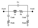
DO you have parametric values for all of the following?
Layout details are critical.

pi.jpg
 

Status
Not open for further replies.

Part and Inventory Search

Welcome to EDABoard.com

Sponsor

Back
Top