Continue to Site

Welcome to EDAboard.com

Welcome to our site! EDAboard.com is an international Electronics Discussion Forum focused on EDA software, circuits, schematics, books, theory, papers, asic, pld, 8051, DSP, Network, RF, Analog Design, PCB, Service Manuals... and a whole lot more! To participate you need to register. Registration is free. Click here to register now.

Why the output power of VCO (Oscillator) is so small?

Alex_Zhan

Newbie level 6
Newbie level 6
Joined
Jan 15, 2020
Messages
12
Helped
0
Reputation
0
Reaction score
0
Trophy points
1
Activity points
181
Dear everyone,

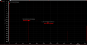
I have designed a VCO operating at ~60GHz, the DC power at the output net is 14.6dBm, while the power of fundamental wave is only ~27.6 dBm? Does anyone know the reason?

Here is the output power, thanks very much!

1678364028183.png

--- Updated ---

~27.6 dBm
-27.6 dBm
 

Attachments

  • 1678363761832.png
    1678363761832.png
    53.1 KB · Views: 20

dick_freebird

Advanced Member level 7
Joined
Mar 4, 2008
Messages
8,246
Helped
2,294
Reputation
4,598
Reaction score
2,337
Trophy points
1,393
Location
USA
Activity points
65,972
I have a question. Why is "DC power" given in dBm?

Standing waves could result in a higher output (reading)
than input power perhaps. This can be measurement
artifact as standing waves result from mismatched line
and invalidate the Z=50 assumption, throwing indicated
power (if figured from VRMS or Vp-p) out the window.

That goes to simulation (or bench) setup. You might be
well off to work in the time domain until you demonstrate
all-proper operation, termination, measurement methods.
Many of the other anlyses are too idealized to debug
setup "by eyeball".
 

dick_freebird

Advanced Member level 7
Joined
Mar 4, 2008
Messages
8,246
Helped
2,294
Reputation
4,598
Reaction score
2,337
Trophy points
1,393
Location
USA
Activity points
65,972
Maybe there -is- DC power, like if it wanted a DC blocking
cap but you didn't give it one? Wouldn't think imposing DC
on what should be a ground referred, controlled impedance
RF output, is common or a good idea.
 

Alex_Zhan

Newbie level 6
Newbie level 6
Joined
Jan 15, 2020
Messages
12
Helped
0
Reputation
0
Reaction score
0
Trophy points
1
Activity points
181
Nobody knows unless you post your schematic and simu

Maybe there -is- DC power, like if it wanted a DC blocking
cap but you didn't give it one? Wouldn't think imposing DC
on what should be a ground referred, controlled impedance
RF output, is common or a good idea.
Dear BigBoss and freebird,

I use the open-drain buffer to output the signal. This is the schematic of the buffer. For better test, I use single-ended output, and the other port is connected by a 50 Ohms resister.
1678413830719.png


Besides, I use the biastee for testing, the OP terminal is the port after the buffer. And I use PSS simulation, I plot the spectrum of the power and show the result above. Why?

1678413978039.png
 

BigBoss

Advanced Member level 6
Joined
Nov 17, 2001
Messages
5,524
Helped
1,574
Reputation
3,150
Reaction score
1,467
Trophy points
1,393
Location
Türkiye
Activity points
33,316
For me, nothing is clear. You're showing a weird buffer but I don't understand what's going on ....
Does the problem occur at VCO or Buffer ?? Why you use differential to single ended ?? What is your essential intention ?? What is the mystery in using Open Collector. You're working on 60GHz and R10 14x4 um ??
 

LaTeX Commands Quick-Menu:

Part and Inventory Search

Welcome to EDABoard.com

Sponsor

Top