Continue to Site

Welcome to EDAboard.com

Welcome to our site! EDAboard.com is an international Electronics Discussion Forum focused on EDA software, circuits, schematics, books, theory, papers, asic, pld, 8051, DSP, Network, RF, Analog Design, PCB, Service Manuals... and a whole lot more! To participate you need to register. Registration is free. Click here to register now.

Please help to resolve this problem about BANDGAP, Thanks!

Status
Not open for further replies.

leonwang

Junior Member level 1
Joined
Dec 6, 2004
Messages
17
Helped
0
Reputation
0
Reaction score
0
Trophy points
1,281
Location
Tianjin
Activity points
113
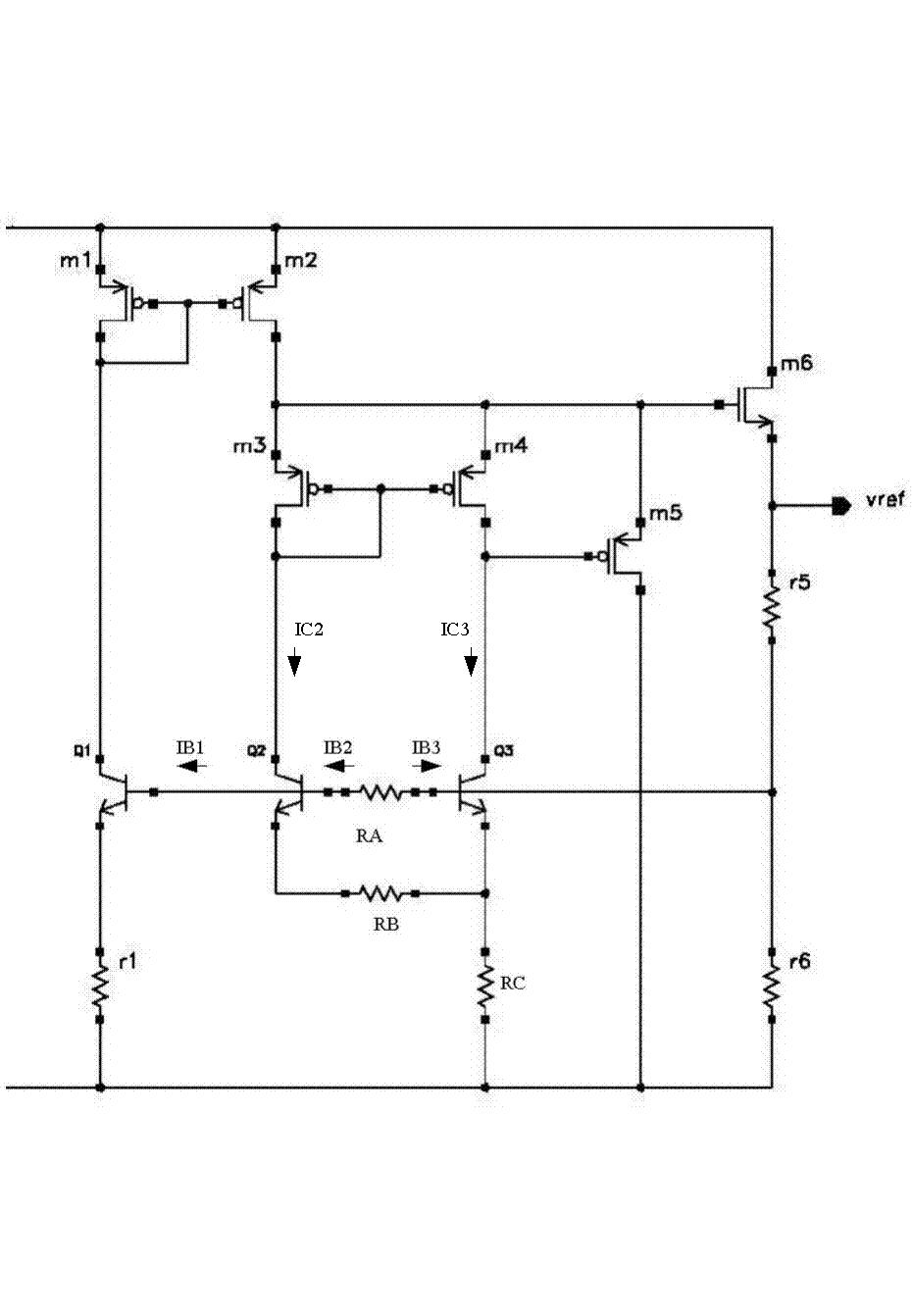
As for the picture in my attachment, you can see a resistor in series with the base of bipolar of a bandgap.

If there is no resistor here, the base current is from r5 and then that will increase the output reference voltage than its nominal value. To decrease this affect, the resistor is put at the base of bipolar.

But, how can I calculate the resistor value ? Could anybody help me?

Thank you very much!!!!!
 

Re: Please help to resolve this problem about BANDGAP, Thank

I am sorry. I added some symbols on your schematic.


Assume:

IC = IC2 = IC3

The emitter area ratio: N = A2 / A3

Have:

VT * ln N = IB1 * RA + IB2 * [ RA + ( BETA2 + 1 ) * RB ]

BETA2 = IC2 / IB2
The VT is thermal voltage.

Select Q1 and r1, so that:

IB1 = M * IB2

The M is a factor.

Then:

IB2 = VT * ln N / [ ( M + 1 ) * RA + ( BETA2 + 1 ) * RB ]

vref = { [ ( BETA2 + 1 ) * IB2 + ( BETA3 + 1 ) * IB3 ] * RC + VBE3 } * ( r5 + r6 ) / r6

BETA3 = IC3 / IB3
The VBE3 is the voltage between base and emitter of Q3.

If:

BETA = BETA2 = BETA3

Then:

IB = IB2 = IB3

vref = 2 * ( BETA + 1 ) * IB * RC + VBE3

Above is my guess, use carefully.
 

    leonwang

    Points: 2
    Helpful Answer Positive Rating
Status
Not open for further replies.

Similar threads

Part and Inventory Search

Welcome to EDABoard.com

Sponsor

Back
Top