Welcome to our site! EDAboard.com is an international Electronics Discussion Forum focused on EDA software, circuits, schematics, books, theory, papers, asic, pld, 8051, DSP, Network, RF, Analog Design, PCB, Service Manuals... and a whole lot more! To participate you need to register. Registration is free. Click here to register now.
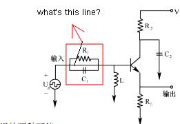
That's not a common defined circuit symbol. Maybe you can conclude from the paper, I unfortunately can't read it. I guess, it could be a transmission line.
Yes, its is a transmission line, as your drawing shows (or problem may be) the Transline here acts as a LC tank circuit which is your transline length(physical) matches to the quarter-of a-wavelength of the applied signal
This site uses cookies to help personalise content, tailor your experience and to keep you logged in if you register.
By continuing to use this site, you are consenting to our use of cookies.