Continue to Site

Welcome to EDAboard.com

Welcome to our site! EDAboard.com is an international Electronics Discussion Forum focused on EDA software, circuits, schematics, books, theory, papers, asic, pld, 8051, DSP, Network, RF, Analog Design, PCB, Service Manuals... and a whole lot more! To participate you need to register. Registration is free. Click here to register now.

Questions about uln2003

Status
Not open for further replies.

gameelgamal

Member level 5
Joined
Dec 14, 2006
Messages
85
Helped
0
Reputation
0
Reaction score
0
Trophy points
1,286
Location
Egypt
Activity points
1,888
uln2003 ic

Hi
I want to use ULN2003 to drive a small stepper motor, and I have some questions

1) What shall I do withe COM pin (pin Number 9), Let it floating or connect it to the supply voltage of the motor???

2) I will use a mirocontroller, Is it right to connect the µc directly to the IPs of ULN2003, In other words, Is the output current of the µc can drive ULN2003 properly??

3) I found this note in the datasheet "The collector-current rating of a single Darlington pair is 500 mA. The Darlington pairs may be paralleled for higher current capability."How can I do that????
 

uln2003

COM pin should be connected to the power supply.
Yes you can connect microcontroller pin direct to ULN.
If you want to increase collector current you can connect 2 input pin(ULN) together at the same pin at uC and the collector pins (ULN) the same together.
 
ic uln2003

I agree with cristi7521
 
function of uln2003

gameelgamal said:
Hi
I want to use ULN2003 to drive a small stepper motor, and I have some questions

1) What shall I do withe COM pin (pin Number 9), Let it floating or connect it to the supply voltage of the motor???
- The pin numger 9, is free (not connect).
2) I will use a mirocontroller, Is it right to connect the µc directly to the IPs of ULN2003, In other words, Is the output current of the µc can drive ULN2003 properly??
- Yes, the output current can drive propely the ULN2003A.
3) I found this note in the datasheet "The collector-current rating of a single Darlington pair is 500 mA. The Darlington pairs may be paralleled for higher current capability."How can I do that????
- Use MOSFET to drive big motors. For small stepp motor, 500 mA is perfect.
 

common free wheeling diodes

yah me too.... this pin is very use full b/c it internally connect collector of all output tarnsistors to the anode of the diodes ...... (refer data sheet). in short u dont need any external diode accros any inductive load to supress back emf like we do when we controll rellays or mottrors through transistros.
 
how to connect uln2003

Recommend some isolation for motor driving.
 
uln2003 why to use

According to the attached picture, could you explain in more detials what is the function of COM pin
 

darlington pair to give 500ma

funnynypd said:
Recommend some isolation for motor driving.

Could you give me some ideas???
 

how to use uln2003

gameelgamal said:
According to the attached picture, could you explain in more detials what is the function of COM pin

Hi,

Usually you connect one end of the coils of a stepper motor to the outputs of the driver IC (OUT1-OUT7), right? Usually the other end of the coils is connected to the positive supply, right? Now if you connect the COMMON FREE WHEELING DIODES pin ALSO to the positive power supply, then you have just connected all the built-in free wheeling diodes as they are needed to protect the IC from voltage spikes coming back from the motor coils at switch-off, ok?
So by connecting the COM to the positive supply where all the other ends of the motor coils are also connected, you have simply placed the built-in diodes in parallel with the motor coils and the diodes will protect the IC.

unkarc

PS: if you read member "drbizzarow" and "cristi7521" answers above, they also referred to the diodes' role and connection.
 
uln2003 pin 9

gameelgamal said:
funnynypd said:
Recommend some isolation for motor driving.

Could you give me some ideas???
I bet that's optical isolation or some isolation chip from TI.
Also ULN2003 was mainly designed to drive relays.
 

uln2003ic

To drive the inductor type of load, it would be good to have some isolation between the micro and the load.
 

thanks thats its give me big benifts.

---------- Post added at 16:30 ---------- Previous post was at 16:30 ----------

thats it my project about uln2804
 

Re: darlington pair to give 500ma

I agree with the design . This was a very correct statement
 

can i connect the input pin of ULN2003 to the port pin of MSP430FG4618? will there be any current mismatch?
also should i use any protection circuit to protect my MSP430 Experimenters board?
 

ULN2003 just needs a few mA from your outputs, it has internal resistance to the input (2k7) to limit the current and is ready to be used for input about 5v , if your mcu is able to give that then you have no problem.

Alex
 
Last edited:

what exactly do u mean by "it had internal resistance (2k7) to limit the current"?
i plan to use the MSP430FG4618 to control a 12V stepper motor thru a ULN2003...dont want the experimenters board to be fried ultimately....
so can i connect it directly?
 

"had" was supposed to be "has", check the internal schematic ULN2003, it has 7 stages like this, one for each input.
The current is already limited by that resistor, you don't need an external base resistor like in a discrete transistor.

ULN2003_stage.jpeg

Alex
 

hmm...ok...hope this works!
 

I suppose your mcu is working with 3v power supply,
in that case the 2k7 will draw about 3v-1v(min saturation voltage)=2v/2700=0.7mA,
Your mcu can give much more than that current,
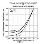
check page 34 of the datasheet https://www.ti.com/lit/gpn/msp430fg4618

msp430fg4618_current.jpeg

Alex
 

Status
Not open for further replies.

Similar threads

Part and Inventory Search

Welcome to EDABoard.com

Sponsor

Back
Top