cupoftea
Advanced Member level 5
Hi,
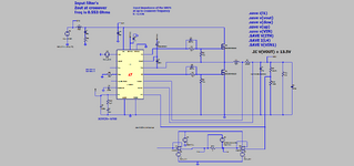
The Vicorpower "DCM design guide" is giving very poor input filter advice.
DCM design guide:
On eg page 12 it is saying that the output impedance of the input filter should
stay MORE than 10 times less than the input Z of the SMPS, up to the crossover frequency
of the SMPS.
Then it shows a "nonsense" diagram of this in Fig 2.2 (a) again on page 12.
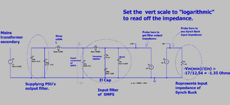
This diagram only achieves "more then ten times less than Zin" due to the ideal voltage source
that is shown there. But no real world source is going to be an ideal voltage source.....it is more likely to be the
output of an upstream SMPS, which is more like a current source followed by a CLC filter....and when you put
such a "real world " source into this diagram, you certainly do not achieve "more then ten times less than Zin".
So why are they showing this very poor advice?
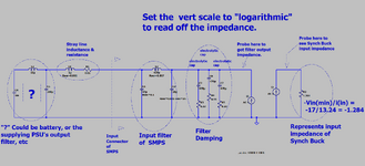
Contrary to what they are saying, the input filter can in fact have an "Output impedance" which is actually even equal to the SMPS zin, -as long as this only occurs at frequencies which are less than 10x the smps crossover frequency.
The Vicorpower "DCM design guide" is giving very poor input filter advice.
DCM design guide:
On eg page 12 it is saying that the output impedance of the input filter should
stay MORE than 10 times less than the input Z of the SMPS, up to the crossover frequency
of the SMPS.
Then it shows a "nonsense" diagram of this in Fig 2.2 (a) again on page 12.
This diagram only achieves "more then ten times less than Zin" due to the ideal voltage source
that is shown there. But no real world source is going to be an ideal voltage source.....it is more likely to be the
output of an upstream SMPS, which is more like a current source followed by a CLC filter....and when you put
such a "real world " source into this diagram, you certainly do not achieve "more then ten times less than Zin".
So why are they showing this very poor advice?
Contrary to what they are saying, the input filter can in fact have an "Output impedance" which is actually even equal to the SMPS zin, -as long as this only occurs at frequencies which are less than 10x the smps crossover frequency.
Attachments
Last edited: