Continue to Site

Welcome to EDAboard.com

Welcome to our site! EDAboard.com is an international Electronics Discussion Forum focused on EDA software, circuits, schematics, books, theory, papers, asic, pld, 8051, DSP, Network, RF, Analog Design, PCB, Service Manuals... and a whole lot more! To participate you need to register. Registration is free. Click here to register now.

Vcc Issue in PWM controller

sabu31

Advanced Member level 1
Joined
Jan 28, 2011
Messages
454
Helped
12
Reputation
24
Reaction score
13
Trophy points
1,298
Activity points
5,215
Hi,

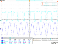
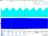
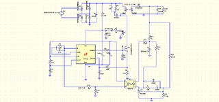
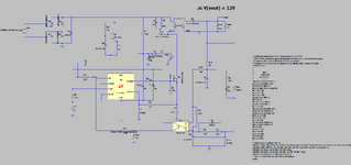
I am making a 12V supply using UC3842. The charging resistor is 50k. However, as I increase the input AC voltage, the Vcc Voltage is fluctuation. What could be the issue?

The converter is a flyback configuration with output at 12V and 12W.
 

Attachments

  • tek00002.png
    tek00002.png
    48.8 KB · Views: 39
  • tek00000.png
    tek00000.png
    40.8 KB · Views: 39
Hi,

increase the value of C14.

Just as a guess, because I miss a circuit, and where you did the measurement. And what´s the input signal of channel 1 and channel 2.
And what is the scale of the two channels .... and so on.

Please understand that we first need useful informations ... then we can help you.

Klaus
The first channel is input ac voltage: Scale : 100V/div

The second channel is Vcc voltage: Scale : 5V/div.

When I give supply 16V supply to the IC externally. It starts generating the sawtooth output and gate output at near maximum duty.

However, when AC voltage is given, the Vcc voltage swings between 15.5 and 10 V. How to know if its due to ULVO.

The sense resistor is kept at 0.15Ohms.
 
It sounds like you are saying that the Vin supply to the UC3842 is not stable?......where is it coming from?, a bias coil, a high voltage linear regulator, or somewhere else?
50k also sounds very high value for the timing resistor in uc3842.

Why not get an equivalent circuit going in LTspice then send it to us here....LT1243 and family are the saem pinout and function as uc 3842, so you can use that. Most probably, when you make out the simulation, you will realise what is the problem.
Yes the Vcc is not stable. The simulation is working fine. I used LT1242 instead of UC3842 for simulation. Its attached for your reference.

But in actual hardware, the Vcc is like a square wave. Its swinging between 16 and 10V. Is there some sort of protection mechanism occurring? Because when I remove the IC, the Vcc point keeps on linearly increasing.
--- Updated ---

Hi,

seems you don´t want to...

Klaus
Hi KlausST, I have attached simulation file for your reference.
 

Attachments

  • Flyback_Discussion.rar
    2.1 KB · Views: 28
Hi,
Got to catch train now, but its basically working here...will pop back later to finish it off.
I had to change diodes as mine doesnt have those
 

Attachments

  • LTspice _TL431 MODEL FROM HELMUT.zip
    1.2 KB · Views: 22
  • Flyback_Discussion1.zip
    3.1 KB · Views: 23
Hi,
Hi KlausST, I have attached simulation file for your reference.
This is a .rar file ... my old tablet can´t open it.
I asked for a schematic. It´shouldn´t be that difficult to post YOUR schematic as a picture.

I wrote "YOUR" in capitals, because I want to emphase that we need the information of the "not properly working" circuit.
As far as I understand the simulation is working properly ... while your REAL circuit does not.

Let´s say you have two (identical) cars. Let´s call them "S" and "R".
Car "R" does not work properly. Car "S" does work as expected.
Which car do you to give to the garage for inspection?

Klaus
 
Hi,

This is a .rar file ... my old tablet can´t open it.
I asked for a schematic. It´shouldn´t be that difficult to post YOUR schematic as a picture.

I wrote "YOUR" in capitals, because I want to emphase that we need the information of the "not properly working" circuit.
As far as I understand the simulation is working properly ... while your REAL circuit does not.

Let´s say you have two (identical) cars. Let´s call them "S" and "R".
Car "R" does not work properly. Car "S" does work as expected.
Which car do you to give to the garage for inspection?

Klaus
Dear Klaus ,

I am attaching the schematic of the circuit of LTSPICE simulation.
 

Attachments

  • Schematci.png
    Schematci.png
    58 KB · Views: 36
Looks to me like you are set up for, and maybe not escaping,
"hiccup mode". I see what looks like a boot winding diode-
OR'd to Vcc, and a skinnky 50K pullup. So every time you
cross UVLO rising, you get one "yip" out the back which (you
hope) will pump the bypass cap hard enough to not hit UVLO
again on the bleed-out.

But I don't know if you can k-couple three inductors at once
(see only one k factor, think got three windingss there ought
to be at least three coupling factors?). The boot winding has the
same L as the output winding and if that's for 5V, will not produce
enough to rectify and get >8V to keep out of UVLO.

Look to that (bootstrep charging) branch and see if it's pulling
its weight.
The output and aux winding have same turns. The output is designed for 12V. Will increasing the resistor R2 (in path of diode in aux charging path) to say more than 25 ohm help. I have tried both 22 ohm and 4.7 ohm, but it has no effect.
 
Hi, its finished now...at least as much as it can be.....if you give spec i will do more for you.
Did you manage to put the TL431 .model into the LTspice sim?...i sent you the .model statement and the symbol above.

The shape of the Vcc voltage you mean...?....it gets charged by your startup resistor at first, then the bias coil kicks in.

It is in nice DCM for you now....which is best for offline flyback.

It takes a lot longer to sim with the leakage L in there...so ill leave you to do that if its ok...chime in if you want more help.

Is this satisfactory for you?...or you dont like it?
 

Attachments

  • Flyback 2.png
    Flyback 2.png
    71.8 KB · Views: 25
  • Flyback_Discussion2.zip
    3.1 KB · Views: 20
Last edited:
Hello - pretty simple - the C on the Vcc charges up - then the flyback starts - but there is insufficient time for the 1000uF output cap to charge ( hence not enough volts out of L3 ) before the cap on the control IC discharges to the point the IC latches out, then the cycle repeats - this is a classic newbie thing.
 
Hello - pretty simple - the C on the Vcc charges up - then the flyback starts - but there is insufficient time for the 1000uF output cap to charge ( hence not enough volts out of L3 ) before the cap on the control IC discharges to the point the IC latches out, then the cycle repeats - this is a classic newbie thing.
The issue was due to the gate resistor being damaged. it was measuring 56k instead of 10 ohm. However, now the regulation aspect needs to be check as output is around 20V.
 
Hello - pretty simple - the C on the Vcc charges up - then the flyback starts - but there is insufficient time for the 1000uF output cap to charge ( hence not enough volts out of L3 ) before the cap on the control IC discharges to the point the IC latches out, then the cycle repeats - this is a classic newbie thing.
..Yes indeed, good point....i changed the 1mF to 47uF straight away to make it quicker to simulate...so didnt run into that problem...I suppose in this way i unintentionally cheated. Does OP wish to re-post latest issue in ltspice and we can assist?
 
A reality-vs-simulation background issue could be
electrolytic capacitor ESL/ESR, which all alone might
make the "reservoir" have too skinny a pipe to cover
switching transient demand and let the at-pins Vcc
sag into UVLO territory. In simulation an ideal cap
will work, but what you can get in value*voltage may
be far from ideal and need you to parallel some
higher-quality lower value ones to give you the HF
bypassing needed.
 
The issue was due to the gate resistor being damaged. it was measuring 56k instead of 10 ohm. However, now the regulation aspect needs to be check as output is around 20V.
aah - damaged from the last blow up - it does seem more likely the new mosfet would have gone POOF ! too, with 56k drive and 15k pull down.
--- Updated ---

Cp and Cz are way too small - in the FB loop

R3 is far too large

R2 is a bit big at 40 ohm
 
Last edited:

LaTeX Commands Quick-Menu:

Similar threads

Part and Inventory Search

Welcome to EDABoard.com

Sponsor

Back
Top