cupoftea
Advanced Member level 5
Hi,
Please help to measure ripple current in an electrolytic capacitor in our SMPS?
Its PFC’d, so we want to measure the ripple current in this capacitor over an n x 10ms interval. (n = 1 or 2 or 3 or ……)
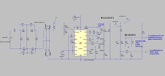
So anyway, we are checking out a novel 150W offline , isolated single stage PFC converter.
I have no schem or BOM as we haven’t payed for it yet. “We are just sampling it” from the supplier.
Its kind of like a Half Bridge, but each switching cycle “stroke” switches from a different capacitor.
One capacitor that gets drawn from is a 33uF, 500V electrolytic in the primary side. Hence we wish to measure the ripple current (RMS) in this capacitor.
I am sensing the ripple current in this capacitor with a 100:1 current sense transformer. Secondary of which is simply a 10R burden resistor. So its sensing at 0.1V/A. (I used a 10:1 probe to measure the burden resistor voltage, and the scope was on 10:1)
I had the scope on 2ms/div, and there’s 10 divisions on the scope window.
At 100VAC input to the converter, and 150W output loading, the “cycle RMS” feature on the scope showed “0.317V”.
…since we are at 0.1V/A, may I assume that this means an AC RMS ripple current of 3.17A? This would seem odd since the capacitor only felt at room temperature (20degC) to touch after I’d switched off.
Anyway, at 240VAC, the “cycle RMS” feature on the scope showed “0.103V”….so again, may we assume this means 1.03A AC RMS ripple current?
Anyway, I wasn’t happy with these readings, so repeated them but this time with the MATH function…So I did the integral with respect to time (dt) of (C1*C1), where C1 was channel 1, the scope probe channel that I was reading the burden resistor voltage with.
Anyway…at 100VAC and 150W, the integral over the 10 divisions of the scope window, (at 2ms/div) gave “167uV^2.sec”.
So we divided 0.000167 by 20ms….giving 0.00835. The square root of this was then taken giving 0.091. But since our system is at 0.1V/A, then this comes out as 910mA AC RMS ripple current?
This is not the same as the 3.17A that was gotten using the “cycle RMS” feature.
How would you interpret these different scope readings?
I must admit, i'm surprised the scope just doesnt let you do......integral with respect to time of i^2 between two cursor points, and use the cursor-to-cursor time interval to do the division....then the answer could be square rooted , and job done. (cursor-to-cursor time being one 10ms period).
The SDS2104x scope has a memory depth of 28MPts.....so for the actual measurement done today, thats one sample every 20ms/28e6 seconds = every 714ps (since there was 10 divisions on the scope screen and it was set to 2ms/div)...that surely should have been enough samples?
The scope used was an Siglent SDS2104x…
SDS2104x User Manual:
Last edited:


