Continue to Site

Welcome to EDAboard.com

Welcome to our site! EDAboard.com is an international Electronics Discussion Forum focused on EDA software, circuits, schematics, books, theory, papers, asic, pld, 8051, DSP, Network, RF, Analog Design, PCB, Service Manuals... and a whole lot more! To participate you need to register. Registration is free. Click here to register now.

Measuring capacitor ripple current with scope

cupoftea

Advanced Member level 5
Joined
Jun 13, 2021
Messages
2,523
Helped
54
Reputation
108
Reaction score
110
Trophy points
63
Activity points
13,202
Hi,

Please help to measure ripple current in an electrolytic capacitor in our SMPS?
Its PFC’d, so we want to measure the ripple current in this capacitor over an n x 10ms interval. (n = 1 or 2 or 3 or ……)

So anyway, we are checking out a novel 150W offline , isolated single stage PFC converter.
I have no schem or BOM as we haven’t payed for it yet. “We are just sampling it” from the supplier.
Its kind of like a Half Bridge, but each switching cycle “stroke” switches from a different capacitor.

One capacitor that gets drawn from is a 33uF, 500V electrolytic in the primary side. Hence we wish to measure the ripple current (RMS) in this capacitor.
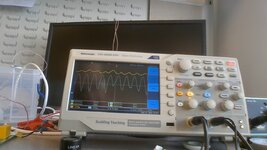
I am sensing the ripple current in this capacitor with a 100:1 current sense transformer. Secondary of which is simply a 10R burden resistor. So its sensing at 0.1V/A. (I used a 10:1 probe to measure the burden resistor voltage, and the scope was on 10:1)

I had the scope on 2ms/div, and there’s 10 divisions on the scope window.

At 100VAC input to the converter, and 150W output loading, the “cycle RMS” feature on the scope showed “0.317V”.
…since we are at 0.1V/A, may I assume that this means an AC RMS ripple current of 3.17A? This would seem odd since the capacitor only felt at room temperature (20degC) to touch after I’d switched off.

Anyway, at 240VAC, the “cycle RMS” feature on the scope showed “0.103V”….so again, may we assume this means 1.03A AC RMS ripple current?

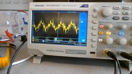
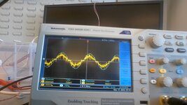
Anyway, I wasn’t happy with these readings, so repeated them but this time with the MATH function…So I did the integral with respect to time (dt) of (C1*C1), where C1 was channel 1, the scope probe channel that I was reading the burden resistor voltage with.

Anyway…at 100VAC and 150W, the integral over the 10 divisions of the scope window, (at 2ms/div) gave “167uV^2.sec”.

So we divided 0.000167 by 20ms….giving 0.00835. The square root of this was then taken giving 0.091. But since our system is at 0.1V/A, then this comes out as 910mA AC RMS ripple current?

This is not the same as the 3.17A that was gotten using the “cycle RMS” feature.
How would you interpret these different scope readings?

I must admit, i'm surprised the scope just doesnt let you do......integral with respect to time of i^2 between two cursor points, and use the cursor-to-cursor time interval to do the division....then the answer could be square rooted , and job done. (cursor-to-cursor time being one 10ms period).

The SDS2104x scope has a memory depth of 28MPts.....so for the actual measurement done today, thats one sample every 20ms/28e6 seconds = every 714ps (since there was 10 divisions on the scope screen and it was set to 2ms/div)...that surely should have been enough samples?

The scope used was an Siglent SDS2104x…
SDS2104x User Manual:
 
Last edited:
This is a lot easier than you think - get a good 100x probe, or 500x probe, set to AC, hook it across the cap

zoom in on the AC so you can see the 100Hz ripple, and the higher freq ripple ( Vrms = Vpp / 2 , /SQRT2 )

Iac = Vac / Xc1, ___ Xc1 -> (100Hz) = 1 / ( 2.pi 100. C )

and similarly for higher frequencies, Iac2 = Vac2 / Xc2 ...

Then add the currents vectorially, e.g. Itot ^2 = I1 ^2 + I2 ^2 + ...
--- Updated ---

you can do this for any cap
 
Thanks but this converter is totally software controlled, and i am not sure what the algorithm is for frequency change, etc....Its quite an unusual converter. This 500V cap is kind of an auxiliary capacitor...its not like the usual post rect bus capacitor.
Unfortunately I cant show the schem that ive reverse engineered from the board they gave us.

I admit that i am only measuring the high frequency stuff, since my CT is too small for the 100Hz.

We are thinking of a cheaper one of like this, so we can do all frequencies down to the 100Hz
Pearson 410

Do you know cheaper versions....we dont need 5000A pk...just say 40A peak....and 5A max rms

Most of the LEM ones dont have the wideband range required.
 
Last edited:
Always second guess the "cycle" measurements on scopes, especially with complex waveforms. The way the scope determines what a "cycle" is may be completely wrong. I would do a full screen RMS measurement, with at least ten cycles acquired (100ms).

Make sure your current transformer frequency response is actually flat below 100Hz. I would advise using a shunt resistor inserted on the ground terminal of the cap.
 
I would advise using a shunt resistor inserted on the ground terminal of the cap.
Thanks, i think you are right...but i think i will need a home-brew coaxial probe to connect up to it to reduce the common mode noise clutter over it...this in turn of course means floating the scope because the isolated AC source is booked up for a while now.........so i will cut off the earth from the scope and just be very careful not to touch it, unless its powered off with all cct discharged.
 
In some ways you are willfully missing the point - looking at the volt ripple on a good scope - it is fairly easy to observe where the minima and maxima are and what sort of densities they have along the half sine - one can then fairly closely ascertain where the average is for the half sine - and go from there ...
 
I was wondering why you wouldn't just take the voltage waveform
and do "capacitor math" on it (maybe, depending on construction,
even as far as extracting ESR, ESL) to get the "must be" through-
current.

Another option I'd consider is to mung a board, cut a trace where
it's handy and sweat on a very low value resistor, and use a TRMS
voltmeter (if that's the thing you want, RMS current, and the meter
is up to whatever the frequency is) - or, use 'scope and use either
its built-ins or export to your own math-grinder.
 
Hi,
Thanks, if this pronciple of measuring the ripple voltage is to work, then AYK, we need to know exactly the ESR of the capacitor..........which isnt well defined or known, and differs in an unknown way at different frequencies...
The attached sim is a BCM flyback, and isnt what i have on the bench here, but you can see from adjusting the ESR a bit (of the output cap) that you have to know the ESR....and i havent started putting ESL in there yet.
Not only that, but ayk, the ripple is a very small signal, and it will be bathed in the usual common mode fuzz.....which of course, the scope wont "know" is common mode noise.
Then if you think of the trace inductance and resistance......it gets even worse for the volt ripple method......i dont have any gerbers for this PCB...just the board...no schem or anything..
 

Attachments

  • PFC Flybk BCM LT3799 150w 240vac.zip
    2.6 KB · Views: 54
Last edited:
Estimating ripple current from ripple voltage is only valid for the very low frequency component of the ripple, where ESR is negligible compared to reactance. And even then the relationship between peak-to-peak voltage and RMS current will depend on the waveform shape (should be sinusoidal for a properly working PFC). And if your ripple current has significant high and low frequency components (like it will for a PFC output), then separating the low and high frequency ripple voltage may be difficult.

And of course, this method will depend on the capacitance itself, which may easily be off by 20% or more.

Honestly I'd expect better accuracy from a theoretical calculation of ripple based on nominal capacitance and average input power. If the voltage-based measurement disagrees with theory, I would be more willing to discard the measurement.
 
Thanks, this converter is single stage PFC....but not a normal one..the 33uF cap on the primary has a highly unusual ripple current in it......this capacitors voltage , over 10ms, sways between 380 to 400V......and has the high frequency ripple (50-200khz) inside that 10ms aswell.
 
The ESR can easily be gauged by the ESR jump in the current signal - you only need to know the approx current at the time of a current step, if the current steps by 1A approx and the voltage changes by 100mV the ESR = 0.1 ohm ...
--- Updated ---

if the voltage swings from 380 - 400V relative to zero volts rectified mains - there will be no CM
 
if the voltage swings from 380 - 400V relative to zero volts rectified mains - there will be no CM
Thanks, though you would agree that the SMPS will still be producing CM noise, and this will couple into the scope lead?...and thereby affect the measurement.
Also, our switching frequency into the cap is varying 50khz-200khz, and ayk, ESR of electro caps varies with frequency....also ayk, some of the resistance/ESL seen will be from the trace inductance /resistance

The thing is , ayk, there's ESL aswell.......just 10n or so of ESL put in the sim above (#10) shows how it completely disfigures the ripple voltage waveform. just a mess of ringing wildness. (HF decaying sines at every switching point)
 
actually ESR of a warm cap - electro - does not vary hugely with freq, tending to be lower at higher freq's

the real world waveforms will be far easier to interpret than a sim - due to parasitic damping R.
 
Thanks, the yellow is the 33uF capacitor, (w.r.t. primary ground) in which we need to measure the ripple current...the blue is the post rectifier primary bus cap. This is when on 150W load at 265VAC in...as you see, there is also a bit of instability.
The blue doesnt always go down to same "valley" point, due to the leakage current of the TA041 diff probe.
So we will put it on AC coupled, home in, and measure up the ripple voltage pkpk with 100:1 probe.

The transformer is 8:1, and vout is 37v, so as you can imagine, only at mains peak is the dc bus cap (blue) being used as source...the 33uF is always used to collect leakage and mag L energy...and when mains goes below 8*37V, the 33uF cap then supplies the "forward" current to the transformer, so to speak.
The ripple "format" in the 33uF cap is thus very different as the 10ms half sine is traversed.

The TDS1052 scope, i will check spec, but i doubt if its going to be very informative down at these low V/div levels.
 

Attachments

  • BLUEV5U6 YELLV33UF 265VAC 150W__after first few secs.jpg
    BLUEV5U6 YELLV33UF 265VAC 150W__after first few secs.jpg
    168.7 KB · Views: 62
Thanks, if this pronciple of measuring the ripple voltage is to work, then AYK, we need to know exactly the ESR of the capacitor..........which isnt well defined or known, and differs in an unknown way at different frequencies...
"exactly" is going a bit far. Depends on how much accuracy you want. What's the nominal ESR of your cap?

The Vout waveform you posted above doesn't look like it has very much high frequency ripple. Try measuring with AC coupling if you want a better look.
 
what does the input AC current look like ?
Thanks, its the attached, which also shows VAC input, for 240VAC, and 150W output.
The trace (yellow) is the voltage across a 0.15R sense resistor in the neutral line.
It looks more sinusoidal (the mains input current) at 100VAC....but has significant dead time at 100VAC...(at the zero crossings, AYK).
This has passed mains harmonics per EN61000-3-2.
3 yr old HA1600A used to test it.
Power factor at 240vac was around 0.89.

Transformer is PQ2625, and is Lp=480uH, Ls = 7.5uH, Llk (sec shorted) = 70uH.
There is no output inductor. (its using the leakage).
I have seen this before, many years ago, it was known as being common back then, but i forget now what was the disadvantages of it.

Also now added IAC input (neutral) when 100VAC input and 150w output.
The transformer is 8:1 Pri:sec.
So when VAC is 100VAC, then it literally cant provide to the output unless it has a voltage of greater than 8*37V = 296V available at the primary side.....now it does have this....by way of the 33uF capacitor......but it must be getting heavily ripple currented in that case.
I am wondering if there is something hidden in that PQ2625 transformer. I am not allowed to take it apart...we have the thing on loan. 8:1 seems like a strange choice. I measured it multiple times with the LCR6200....and checked other known inductors with it just to check the LCR6200 out.
 

Attachments

  • 240vac 150w VACin IACin.jpg
    240vac 150w VACin IACin.jpg
    202.4 KB · Views: 56
  • 100vac 150w pfc 0r15 60Hz.jpg
    100vac 150w pfc 0r15 60Hz.jpg
    171.2 KB · Views: 61
Last edited:

LaTeX Commands Quick-Menu:

Part and Inventory Search

Welcome to EDABoard.com

Sponsor

Back
Top