Continue to Site

Welcome to EDAboard.com

Welcome to our site! EDAboard.com is an international Electronics Discussion Forum focused on EDA software, circuits, schematics, books, theory, papers, asic, pld, 8051, DSP, Network, RF, Analog Design, PCB, Service Manuals... and a whole lot more! To participate you need to register. Registration is free. Click here to register now.

How to arrest the noise signal in the bridge output during contactor on/off

Status
Not open for further replies.

prakashvenugopal

Advanced Member level 1
Joined
Jun 1, 2011
Messages
473
Helped
15
Reputation
30
Reaction score
15
Trophy points
1,298
Activity points
4,973
Hi all,

I am facing the issue of noise signal comes into my bridge rectifier circuit through transformer 220v.

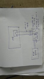
I am using 220v ac primary --> 22-0-22v secondary. This secondary output is given to bridge rectifier circuit with 2200 uf electrolytic capacitor in the bridge output --> regulator

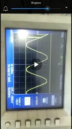
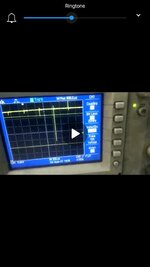
I am switching ON/OFF the contactor in the same line of transformer 220V ac. Huge noise seen in the bridge rectifier output during contactor ON/OFF. This is reflecting in the regulator output also.

How to solve this noise? Kindly help.

I am attaching the noise signal seen during contactor on/ off in the transformer seconary waveform 0-22v ac measured in oscilloscope and also bridge output signal. Kindly check and please help.

Regards,
V. Prakash
 

Attachments

  • Screenshot_20210814-192500.jpg
    Screenshot_20210814-192500.jpg
    813.1 KB · Views: 161
  • Screenshot_20210814-192538.jpg
    Screenshot_20210814-192538.jpg
    416.2 KB · Views: 163

Solution
Hi,

these signals are fast. Thus you need a fast capacitor.
Often huge capacitors a slow capacitors.

--> thus add a 1uF ceramics in parallel.

But all this does not help if youhave bad wiring / bad layout.

Klaus
The OP reports an actual malfunction - but does not specify exactly what form this takes.

regardless, turning the mains Tx on and off every 2 sec continuously will lead to a real malfunction before long ....
 
Hi,

25 mhz ferrite bead cable snap ferrite and 300khz cable snap ferrite @ source of the transformer secondary reduces my problem to 50%.
For your information.

Regards,
V. Prakash
 

At the junction plug where the contactors and input to the transformer wire taken. Attachment made.

Regards,
V. Prakash
 

Attachments

  • IMG_20210820_120034.jpg
    IMG_20210820_120034.jpg
    1.1 MB · Views: 122

Yes. It is an malfunction. Not an measurment artefact.
Probably both. The spikes are not actually on the power supply output, but they reach the connected circuit.
Attachment made.
Is it asking too much to expect a readable (e.g. upright) picture?

1629451424722.png


25 mhz ferrite bead cable snap ferrite and 300khz cable snap ferrite @ source of the transformer secondary reduces my problem to 50%.
Sounds reasonable. You didn't yet report what's the function of the connected circuit and what kind of malfunction was observed.

You showed that common mode chokes reduce the effect of mains transients to your circuit. The actual problem is the noise succeptibility of your circuit, e.g. due to bad layout, missing built-in supply and signal filtering etc.
 
i now give you a PCB layout doc so you can reduce noise problems (attached)
 

Attachments

  • Basics of SMPS Layout _4.zip
    543.1 KB · Views: 71
Hi,

a transformer with an earth screen between pri & sec, would be very helpful to you too -- and would likely solve your issues.


"You mean isolation transformer"?

Regards,
V. Prakash
 

No, very few these days, it appears you have not looked up earth screen for transformers - google is your friend

can you explain how an earth screen blocks CM interference ?
 
Hi,

can you explain how an earth screen blocks CM interference ?

Yes. That is the question i am thinking to ask. How common mode noise will be solved in earth screening of the transformer.?

Regards,
V. Prakash
 

10 sec google search gives....

--- Updated ---

1629959980407.png
 
Hi,

Here we follow this type of transformer only. I had tried with 1:1 isolation transformer also.
230V ac to 230V ac isolation transformer --> my panel transformer input.

Regards,
V. Prakash
 

Hi,

It seems you don't understand capacitive effects within a transformer.

With a usual transformer there are pri and sec next to each other, thus there is capacitive coupling between pri and sec.

With a trasformer including an Earth shield winding, pri and sec are not next to each other anymore. Thus no capacitive coupling.

Klaus
 
Status
Not open for further replies.

Part and Inventory Search

Welcome to EDABoard.com

Sponsor

Back
Top