Continue to Site

Welcome to EDAboard.com

Welcome to our site! EDAboard.com is an international Electronics Discussion Forum focused on EDA software, circuits, schematics, books, theory, papers, asic, pld, 8051, DSP, Network, RF, Analog Design, PCB, Service Manuals... and a whole lot more! To participate you need to register. Registration is free. Click here to register now.

[SOLVED] Can I unplug cell phone antenna?

Status
Not open for further replies.

Chipsmoker

Newbie level 6
Joined
Dec 2, 2020
Messages
12
Helped
0
Reputation
0
Reaction score
0
Trophy points
1
Activity points
123
I have a 1992 Motorola mobile phone that came installed in a vintage sports car we recently purchased. I want to preserve it for historic reasons and to keep the car as original as possible.

I realize the AMPS technology is long since obsolete so the phone is essentially a brick, but the buttons light up and beep when pressed so that’s cool.

I am concerned, however for the safety of those in the car. This phone operates at 3 watts and the antenna is mounted on the windshield putting it within a foot or two of the passenger’s head.

Since it cannot make calls anyway, would unplugging the antenna from the transmitter, eliminate any RF or will the transmitter itself be able to emit RF? Will doing so cause harm to the transmitter?

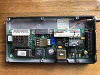
Thanks so much for reading this post. Here is more detail about the phone:

Installed by car maker in 1992 in a new car.

The handset is Motorola SCN2462A

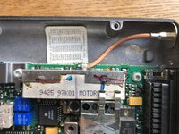
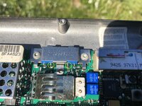
The transmitter is Motorola S4015A FCC ID: IHDT5SZ2

TX power output 3 watts
 

If you can find an antenna conector or connector and lead then make up a 50 Ohm load that can handle the 3 Watts. Disconnect the antenna and replace it it with the load. This will keep the antenna cabling and the phone in original condition and prevent the phone from potentially causing too much interference if it does transmit. The 3 watts is not much different to current handheld phones and since most people seem to be reluctant to be out of physical contact their devices for more than a few moments I wouldn't get too wound up over a short transmission from a car phone with an antenna external to the vehicle.
I can't find any data on the phone, the FCC report does not seem to be on line so am unable to advise on the connector type. Just make sure that the resistors are screened and have very short leads (preferably surface mount types) and you should not have too many problems. Search for dummy load if you are unsure of what I mean.
 

    Chipsmoker

    Points: 2
    Helpful Answer Positive Rating
Thanks G4BCH,

FCC data can be found here: https://fccid.io/IHDT5SZ2

I never thought of the interference issue. Good point! I wonder if the transmitter can be disabled either through programming or cutting traces.
I do know that the antenna connector is a BNC coax. It detaches easily at the transmitter.
 

BNC tterminations are readily available, but get quite expensive for greater than 1W. If you only allow the transmitter to be o for a short time a 1W load will handle it wihout getting too hot.
Making your own higher power load should be easy if the connector is a BNC. You can mount a 50 Ohm termination on a heat sink at the end of a piece of cable and place it where it it convenient. If you do make your own you do need to be careful with its construction, although I said search for dummy load, after having done so myself to check most of what is easily found is not going to work at 900MHz. The best I found was
https://www.nutsvolts.com/magazine/article/build-a-small-powerful-dummy-load
It is not quite what you're looking for but shows how to keep the leads short for use at high frequency. For 3W you don't need too water cool it.

I doubt that it would be easy to re-program to disable the transmitter. I assumed that you would not want to damage the unit by cutting tracks. It may be posssible to disconnect the transmitter stage amplifier power cable or lift a component on the PCB. You would need to look at the unit to determine the easiest option.
I have seen in side an old mobile phone once and from what I remember the output stage was an integrated assembly, the power to those is usually fed in via an indictor that can be lifted from the board. Keep it safe incase you want ot replace it, searching for the phone it seems that these old parts in good condition are quite valuable.
 

    Chipsmoker

    Points: 2
    Helpful Answer Positive Rating
That's a great article on dummy loads. Thanks so much for sharing.
I have not yet cracked open the case on the transmitter or I guess more correctly I should call it the transceiver?

I am the curious type so I will have a peak inside. I actually don't mind cutting or removing components as long as the essential function of the handset remains intact. That being that the buttons light up, beep when pressed, and display numbers on the 7 digit LCD display. The reason I don't mind permanently disabling the transmitter is because it can never connect to any cell tower in North America or most of the world for that matter. Cell tower support for AMPS phones ended over a decade ago, so the phone is a brick now anyway. I have nothing to lose by disabling the transmitter.

BTW, I tried feeding the required 9.5 volts to the handset from a power supply (thus eliminating the transceiver entirely) and the buttons light up, but nothing happens when they are pressed. I want to get the pretend functionality of the phone but without the RF and preferably without the 3 watt draw on my car's electrics.

Having said that, I wonder how often the transceiver tries to locate a tower? The RF would presumably be a short burst at full power, repeated every so often but I cannot imagine it would continuously search for a tower. Oh well, it is interesting and I am learning lots. Thanks again!
 

the easiest is indeed just hooking a 50 ohm load at the transmitter output. you will want one that can handle to transmitted power, which i suppose can be as much as 3 watts. So when you hook one on, if it is getting very hot to the touch, you might end up with a fire hazard.
 

    Chipsmoker

    Points: 2
    Helpful Answer Positive Rating
Thanks biff44 and G4BCH,
So, as a noob and someone who only knows enough about electronics to be dangerous (hence the name Chipsmoker) how did you guys determine that I need a 50 ohm load?
 

Standard impednce for communications antennas.
TV antennas and video signals usually use 75 Ohms. Radar video sometimes 93Ohms.
 

    Chipsmoker

    Points: 2
    Helpful Answer Positive Rating
Before building a dummy load that could be a fire hazard, I tried Motorola Test Mode Programming. Although I was able to change lots of settings, it seems I could not make a permanent change to the power level of the transmitter or to turn off the transmitter. :(

So I cracked it open to have a look inside.

As stated before, I don't mind making a permanent change to stop this thing from ever transmitting to the antenna. Anyone see any clever way to do this? I have attached two photos.
 

Attachments

  • IMG_3480.JPG
    IMG_3480.JPG
    4.3 MB · Views: 166
  • IMG_3481.JPG
    IMG_3481.JPG
    3.4 MB · Views: 149

The block with the antenna connector is a transmit/receive duplex filter isolting the transmit and receove paths.
The power amplifier is the blue device unde the clamp labelled 07......
If it is like other Motorola power bricks connections are left to right:
RF input, Input stage power supply, Output stage power supply, RF output. Ground is via the heatsink.
Diconnect the power connections, snip or lift the wires put of the holes.
The output connector looks like it is a TNC rather than BNC, it is threaded rather than bayonet mating.
 

    Chipsmoker

    Points: 2
    Helpful Answer Positive Rating
Fantastic! It sounds like the solution I was looking for. My apologies for not correctly identifying the antenna connector type. I am still learning.
So just to confirm before I cut the power connections, I will cut the two chip leads that are circled in yellow on the attached picture?
 

Attachments

  • Amp cut.jpg
    Amp cut.jpg
    3 MB · Views: 149

Oh and one final question (I hope). Will this modification still allow a very small amount of RF to the TNC connector? I assume the answer is no, or that it will be at such a low level as to be inconsequential. Just wondering if I should leave the antenna connected or not.
 

If you want to be sure that the residual radiation is minimal remove the input and output capacitors to the power amplifier, left and below the input connection and to the right of the ouptut connection. The output will probably only be a few microwatts if you leave it as it is. The drive to these modules is only a few milliwatts and with the power disconnected the loss through the amplifier should be quite high.
Looking again at the connector it may be an F type, as used on satellite TV caables, not that it matters if you are not looking for another connector.
 

    Chipsmoker

    Points: 2
    Helpful Answer Positive Rating
Ok, so I took a depth breath and cut the leads for pins 2 and 3 on the RF power amplifier. I then powered up the phone to see if the buttons and other functions still worked. Everything still functions great!!! The buttons light up and beep when pressed and the digital display on the handset functions perfectly. Mission accomplished!

The last step, if I decide to go there, is to buy, borrow or build an RF or field strength meter to measure any actual remaining RF energy. I seriously doubt there is any to be concerned about.

Thanks again G4BCH. I could not have done this without your help and patience.
Cheers!
 

Status
Not open for further replies.

Part and Inventory Search

Welcome to EDABoard.com

Sponsor

Back
Top