Continue to Site

Welcome to EDAboard.com

Welcome to our site! EDAboard.com is an international Electronics Discussion Forum focused on EDA software, circuits, schematics, books, theory, papers, asic, pld, 8051, DSP, Network, RF, Analog Design, PCB, Service Manuals... and a whole lot more! To participate you need to register. Registration is free. Click here to register now.

[PIC]Is this design good to measure 2mV to 8mV ? [Load Cell]

Status
Not open for further replies.

Okada

Banned
Joined
Jun 16, 2016
Messages
1,159
Helped
129
Reputation
252
Reaction score
129
Trophy points
63
Activity points
0
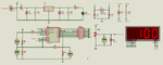
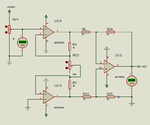
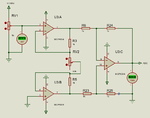
Is this design good to measure 2mV to 8mV ? I am using CZL928E Load Cell.

https://hlhsensor.en.made-in-china....X/China-Micro-Weighing-Load-Cell-Czl928e.html

Test the attached Proteus Simulation. Opens in Proteus 8.5 SP1 or later.

I had to measure 2mV to 6mV and display it a 0 to 100 (percentage) but I designed to measure 2mV to 8mV. For people who doesn't have Proteus I have attached the circuit in image format.
 

Attachments

  • Load Cell Measurement.png
    Load Cell Measurement.png
    37 KB · Views: 171
  • Load Cell Measurement.rar
    27.5 KB · Views: 88

Thers is a small bug in adc calculation. Have to apply y = mx + c using linear regression calculator. The current values provided by my client is not correct. Will post new project after fine tuning.

- - - Updated - - -

Here is the fixed project. Just the simulation.
 

Attachments

  • 08102016.rar
    33.4 KB · Views: 94

I don;t have Proteus so the files you have attached are of no use as we really need to see the source code.
My concern is that the difference between 2mV and 8mV is quite small. Therefore I'm assuming that you are using the FVR so as to obtain the lowest possible ADCref+ voltage - but even that is 1.024V. As the ADC is 10 bit, that means it will measure in 1mV steps.
Also as you are outputting a percentage, can we assume that you are wanting a +/-1 digit accuracy - that would equate to trying to measure the input to about +/-10uV. At this range you will probably have trouble with noise on the input.
Also that does NOT fit with the available range of the ADC.
I would suggest that you use an op-amp connected to the load cell to boost the voltage in as noise-free a way as possible and then try to measure the amplified voltage with the ADC.
Susan
 

I am using PIC's internal Op Amp to amplify the 2mV to 8mV signal to 0 to 5V for ADC.
 

Due to proprietary reasons I can't post the code. Only one segment of a digit is turned On at a time and hence the 3 transistors and their associated resistors used to drive the common cathode pins of the displays are eliminated. Only 10 to 15 mA current flows through each common cathode pin at one time and hence PIC pins can directly drive them. Here is the Proteus Simulation Video.
 

Attachments

  • Proteus Simulation Video.rar
    70 KB · Views: 82

Hi,

This is your third thread about the same topic.

The problem stays the same: our answers can only be as good as your informations.

You dont say what precision you expect. We can not know this.
I assume you want to measure DC voltage of your sensor.
And I assume you want you want 1% precision

Then your design surely is not suitable.
Your sensor gives 2mV....8mV, the range is 6mV.
Your opamp adds (unknown) -3mV ... +3mV of offset. This is 6mV of of error range.
******
If (we don't know) you are interested in AC only, then you may cancel out the offset error.
If you just want to measure the difference between two weights, then you may cancel offset errors.
But in both cases you need to take care about opamp output voltage range. (Virtual opamp input = load_cell_out + Opamp_offset = -1mV .... 11mV)
******

If (we don't know) you want 1% precision, then your opamp input errors need to be smaller than 6mV x 1% = 60uV.

For DC performance the opamp errors mainly are: offset voltage, offset voltage drift, noise
For pure AC performance the errors are: noise and a part of the offset drift.

Klaus
 

I am using PIC's internal Op Amp to amplify the 2mV to 8mV signal to 0 to 5V for ADC.
The specified OP offset voltage is in the same order of magnitude as your load cell voltage. You might be able to operate the circuit in a simulation but it's surely no reasonable design.

I assume that the load cell has a bridge configuration and needs an instrumentation amplifier to process the signal.
 

@KlausST

I will provide more information when I get them. My client has not provided sufficient information. I am only measuring 2mV to 6mV DC. In post one I have mentioned the Load Cell used.

@FvM
Then what should I do to improve the design ?
 

***********

Hi again

About your post #5:

If only one sgment is ON at a time, then you have a 1:7 or 1:8 multiplexing rate.
This also means you get 1/7 or 1/8 of the specified brightness.(max)

Usually this is compensated by using 7 times or 8 times the specified DC LED current.

If you do this, then you have to expect 2 digits x 7 segments x 10mA = 140mA total disply current for displaying " 88".
This is the same as for non multiplexed displays.

Klaus
 

@FvM

Can I use this ?

https://www.linear.com/product/LT1167

@KlausST

If you do this, then you have to expect 2 digits x 7 segments x 10mA = 140mA total disply current for displaying " 88"

I didn't get this. Explain more clearly. In my setup one segment out of 8 segments (a, b, c, d, e, f, g, dp) turns ON at a time. Due to 33oE resistor the current limits to 10 mA. Do you say that display brightness will decrease ?
 

Hi,

I clearely wrote:

This also means you get 1/7 or 1/8 of the specified brightness.(max)

Klaus
 
  • Like
Reactions: Okada

    Okada

    Points: 2
    Helpful Answer Positive Rating
LT1167 can be used, but a 5V single supply rail-to-rail instrumentation amplifier is preferable because it utilizes the full ADC spa without additional power supplies.
 
  • Like
Reactions: Okada

    Okada

    Points: 2
    Helpful Answer Positive Rating
Hi,

going through your other threads...

I doubt that the 2mV and the 8mV are true. Where from do you have those values?
It seems you didn´t do a search for load cell amplifiers. Are you aware that you use a 4 wire sensor with two ratiometric outputs? At least your schematic doesn´t show this.

I recommend to read some datasheets and application notes about load cells, theirs signals and amplifier circuits.

Klaus
 
  • Like
Reactions: Okada

    Okada

    Points: 2
    Helpful Answer Positive Rating
I only have the datasheet of the load cell and I have not read it in full. My client has provided the those voltage values. All I was told is, 2mV has to be displayed as 0 and 6mV as 100.

- - - Updated - - -

@FvM

Can I use this with 5V supply to Op Amp ?

https://www.linear.com/product/LTC6800
 

Hi,

if this is the specification of your client, then you are safe. (lucky you)
This means all the problems of the load cell is not your problem.

I´d make the calibration with known voltages, means generated with a couple of resistors. Calibration with software.
But for sure you have to take care about noise and offset voltage drifts.

Use a calibration aid like this:
mV_Ref.png
All resistors 1%.
The nominal adjust range is +/-2%. Use exactely 5.000V input.

Klaus
 

Attachments

  • LCM.zip
    30.8 KB · Views: 93
  • IA.png
    IA.png
    21.5 KB · Views: 102
  • IA2.png
    IA2.png
    37.4 KB · Views: 94

With single power supply this schematic will not work correctly even if you are using rail-to-rail amplifier.
 
  • Like
Reactions: Okada

    Okada

    Points: 2
    Helpful Answer Positive Rating
A single supply instrumentation amplifier can't provide common mode range down to ground, even with ideal rail-to-rail OPs. At least one OP output will be saturated.

The simulation setup is however inappropriate for a load cell. If the amplifier uses the same supply as the load cell, you have common mode voltage at mid supply and everything is fine. E.g. load cell with 5V single supply has differential output voltage centered at 2.5V.
 
  • Like
Reactions: Okada

    Okada

    Points: 2
    Helpful Answer Positive Rating
Then what is the solution ? Use +5V and -5V power supply for OpAmps ? For now I am testing only in Proteus. Just now I ordered 5 pieces of MCP6004 Op Amps. Before they reach me I want to keey the circuit ready.

This is the link to Load Cell.

https://hlhsensor.en.made-in-china....X/China-Micro-Weighing-Load-Cell-Czl928e.html

Excitation voltage is 9V to 12V.

12V is used for excitation.

Load Cell has three wires. Red wire goes to 12V, Black wire to GND and green wire gives 2mV to 4mV.

What is the best way to design an amplifier for this using either single or dual power supply ?

12V SMPS adapter is used for the power supply. It gives 12V excitation voltage and a 7805 is used to get 5V for PIC.
 
Last edited:

Status
Not open for further replies.

Part and Inventory Search

Welcome to EDABoard.com

Sponsor

Back
Top