Continue to Site

Welcome to EDAboard.com

Welcome to our site! EDAboard.com is an international Electronics Discussion Forum focused on EDA software, circuits, schematics, books, theory, papers, asic, pld, 8051, DSP, Network, RF, Analog Design, PCB, Service Manuals... and a whole lot more! To participate you need to register. Registration is free. Click here to register now.

Impedance Matching in Patch array 60 Ghz

Status
Not open for further replies.

mirou

Member level 1
Joined
Jul 23, 2016
Messages
40
Helped
0
Reputation
0
Reaction score
0
Trophy points
6
Activity points
293
Hello evey body,

Anybody can help me i'm a student and i'm new with hfss and patch arrays.
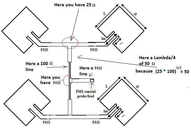
i would like to Match 50 Ohm line to 50 ohms Patches in my feed network of 2*2 microstrip array but i can't how can i do it and how can i design the Feed network.
if any body have a picture which include the impedance of each line sent it to.
I try with a picture with include 50 and 70 ohms line but no way.
It is obligatory to work with 100 ohms line !!
Please help me 60 GHz feed network.jpg
 

It is obligatory to work with 100 ohms line.
Your exercise problem seems to want one 1:4 splitter instead of 3 1:2 splitters.
 

Dear Fvm,
i can't understand, i'm using λ/4 transformer i use lines of 50 ohms and 70 ohms to Match impedance is it true ??
50-70-50-70-50 is this matching true ? Or i must use 100 ohms line Too.
I will see you the picture of My microstrip 4 Patch array antenna.
Patch array antenna.jpeg
 

Hello again,
i wish that any body can help me. I'm improved my Feed Network by using lines of 100 ohms but i found a bad S parameter.
I found that S11 equal to -2db is it a problem of Bends or what ??
Thanks in advance.
 

Hi,
Your patches are a 50 ohms-impedance so , two patches in parallel give rise to 25 ohms at your " T " junction. So after your "T" you must find a quarter-wave transformer of 50 ohms caracteristic impedance that is attached to a 100 ohms line and finally two 100 ohms parallel impedance (your two networks of two patches) give the desired 50 ohms impedance matching.
But effectively be carrefull of the bend it give rise to reactif impedance. To solve this problem make an "optimization" or a parametric study with HFSS (for example the lenght of your lambda/4). Make a good symetric feed-network. Usually all works very well.

Bye.
 
Hello Dear Eraste,
Thanks for you reply; i'm applied all conditions of impedance Mathcing i'm used a Lambda /4 transformers and lines of
50 and 70.7 and 100 ohms but the problem persists i think it was a problem of Bends Do you have any idea how to design this bends using HFSS and thanks for avdance

You can see pictures1.png2.jpeg
 

Hello
Thanks for your Reply BigBoss but how can i do this type Of bends using HFSS !! really i'am blocked.
Can any one help me with a tutorial or explain to me how can i do it with easy method using HFSS.
And Thanks For advance.
Bend 90 degree.jpeg
 
Last edited:

Hi mirou,
first : Have you made any optimization with HFSS ?
second : why did you choose a 70 Ohms lambda/4.It's possible but a little bit complicated, I think.
If your two patches are 50 Ohms at the "T" junction you've got 25 Ohms so after the "T" you must change this 25 Ohms impedance with a 50 Ohms-lambda/4 transformer to give a 100 Ohms impedance. Finally you 've got your 50 Ohms to connect to the main line (100//100 = 50) . In this case you have only two lambda/4 transformer instead of four.

I suggest you to made an optimization for the lambda/4 attached to the "T" junction (in width and lenght). At the end, your matching will works well...

Regards.
 

Hello Eraste,
i have seen a picture that contain a 70.7 ohms lambda/4 transformer
i can show you this microstrip Patch antenna array below but what i have to do really i can't understand
Which lines must be changed to lambda/4 transformers 50 or 70 can you draw to me
a picture to understand what i have to Do. i have made an optimisation for the lambda/4 transformer i know the exact length and width
Thanks for advance
image41.png
 

Hi Mirou,

This is my suggestion.
You have in that picture two Lambda/4 transformers.


Regards.
 

Good morning Dear Eraste,
Thank you very much for your reply and for The picture
i will trying to do your idea and i will show you the results
Thank you again for your help.

- - - Updated - - -

Hello Eraste,
what do you think about this calculator here we have to Match a 50 and 100 ohm lines
we have to use a line of 70.71 ohms !!
Sans titre.png
 

Hi,
No because, 50 ohms in paralell with 50 ohms gives rise to 25 ohms so you have to transform 25 to 100 ohms and not 50 to 100. Consequently the transformer used is a 50 ohms caracteristic impedance ...do the calculus...
Bye
 

Hello Eraste, hello every one

I want to say that i can't do my matching i can't find a best results of s11 i'm trying all methods of matching and no way
i Try your suggestion but no way always S11=-2db it's a worse result can i sent to you on your mail the Hfss file of my patch array.
Can any body help me to inscrease the Gain and said to me which matching can i do in my 4 microstrip patch array.
i use the technique of corporate Feed network and i want to know how to match my lines because really i was blocked.
My Friend Eraste you can find in the picture your suggestion and my suggestion but no way always i found the same result of Gain.
Matching 1.pngMatching 2.pngResult.png
 

Hi Mirou,
Well, are you sure of the patch impedance (50 Ohms). Did you determine it by simulation ? Or calculus ? You can, in a first time simulate the feeder alone by placing a 50 Ohms impedance instead of the patch element.
This will permit you to know if the feeder is well done ...
If you want to send me your project (send me a private message) , i will have a look on it .
Regards.

- - - Updated - - -

Just a precision,

On the schematic i have send to you, you cannot feed by a probe. Only by a lumped-port a the edge of the substrate (practically by a SMA-socket for example). But at 60 GHz which socket will you use ?

See you later.
 

Hello again Eraste,

Yes i have simulated the single Patch and it give me a best result of S11
and than i have changed the Patches To 100 ohms but no way always i find a bad result of s11.
you can see in the picture the result of my single Patch and i will send to you in private my work to
see what's the problem.
Single.jpeg
 

Hello Eraste,Hello every body,
Can any one help me to increase the Gain of my Patch antenna
i have used this type of matching in the picture one(50ohm-70.7ohm-50ohm-70.7ohm-50ohm, and i have finded the result in the picture 2 but as you see the Gain in not good and S11 is bad.how can i increase the value of S11 to be <-10 db.
Picture one technique of impedance.jpgPicture1 the result.jpeg
 

S11 magnitude is about the minimal information you can get from the simulation. Why not showing complex S11 (Smith diagram) to clarify what the actual input impedance of the antenna group is. Did you already try the suggestion by eraste to check the matching network with 50 ohm resistors replacing the antennas?

It should be always possible to get good S11 for a single frequency by tuning length and width of the matching elements.
 

Hello Dear FVM

Yes i'am tested the suggestion of Eraste and no way but this matching i think is good.
(50ohm-70.7ohm-50ohm-70.7ohm-50ohm)
how can i increase the value of S11, is it by modifing the width and length of Patches ?
What parameters I need to modify to improve the Gain and the value of S11.
And Thanks for advance
 

Status
Not open for further replies.

Part and Inventory Search

Welcome to EDABoard.com

Sponsor

Back
Top