Continue to Site

Welcome to EDAboard.com

Welcome to our site! EDAboard.com is an international Electronics Discussion Forum focused on EDA software, circuits, schematics, books, theory, papers, asic, pld, 8051, DSP, Network, RF, Analog Design, PCB, Service Manuals... and a whole lot more! To participate you need to register. Registration is free. Click here to register now.

2N3866 RF Amp Simulation in Microwave Office - Need In & Out impedance

Status
Not open for further replies.

Geryhold

Newbie level 5
Joined
Jun 22, 2016
Messages
8
Helped
1
Reputation
2
Reaction score
1
Trophy points
3
Activity points
66
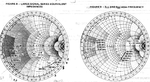
I need details 2N3866 of In & Out impedance (real and imaginary) for a frequency of 150 MHz. I found datasheets https://www.kitsandparts.com/2N3866.pdf Motorola, and there is a a graph SMITH impednsom and S parameters. But unfortunately the low quality of document and I cant read the required data to me. Help me please.

smith_2n3866.jpg
 

Here be a lesson to all, never throw away old data books that contain potentially useful information and just rely on being able to down load it again at any time.

It is hard enough trying to read the impedances from the original let alone a pdf of a scan.

As near as I get estimate the input impedance at 200MHz is 4 - j15 ohms and the output is 160 - j35 ohms.
What it will be at 150MHz you will have to estimate yourself. Allow some tuning I would guess that a 2N3866 made now will not be like one made when that data was taken. About all you can say is the impedances will likely be in roughly the same part of the chart and follow a similar path.
Peter

Thank you for your answer, I understand you have a Smith chart in good quality and were compared with chart documentation that Motorola.

I understand to 200MHz on the graphics input value Re (0.08) -j (0.3) and should be hi impedance 50 ohms, it will be Re = 0.08 * 50 = 4 Ohm and j = 0.3 * 50 = 15. As a result, we get Zin = 4 - j15.
All the same for Zout, very strange but I have to get another value according to the schedule of documentation Motorola Re = 0.8 * 50 = 40 ohms, and j = 2,7 * 50 = 135. As a result, we get Zout = 40 - j135, and you it turned 160 - j35. Maybe I'm wrong or incorrectly believe.

Now let's try to identify the frequency of 150 Mhz input and output impedance. I managed:
For Input Re (0.07) -j (0.4), leads to resistance of 50 ohms, it will be Re = 0.07 * 50 = 3.5 Ohm and j = 0.4 * 50 = 20. As a result, we get Zin = 3.5 - j20.
For Zout, Re = 1 * 50 = 50 ohms, and j = 3.5 * 50 = 175. As a result, we get Zin = 50-j175 ohms.

Please check me out.

smith_chart_full_size_excelhero.com.png
 
Last edited:

Here is a scan from my 1978 Motorola RF data book.
 

Attachments

  • 2N3866.png
    2N3866.png
    892.6 KB · Views: 237
That's great , thank you very much , tell me in my top post, I correctly identified impelansy ? And why we have studied different values ​​for the input impedance at 200MHz ?
 

E-design has a better old data book than I have; I've got an old RF databook at nome, but here I've only got the small signal transistor book from 1983. The smith chart in that is tiny, I needed to use a microsope to try to read it. I read it in a bit of a hurry and had difficulty getting the book postitioned so I could read it, as a consequence I got the real and imaginary parts of the impedance swapped while writing it down.

I found a link to an RCA datasheet that has impedance data to 150MHz

https://www.electro-tech-online.com/attachments/datasheet-14-pdf.32742/
as part of this thread
https://www.electro-tech-online.com/threads/rf-signal-amplification.96153/page-4

and they are completely different from the Motorola data.

If you can you may well be beter off measuring the device you have. These generic parts can differ markedly from one manufacturer to another, ther eare only a few parameters that are controlled; current gain, ft and maximum voltages are about it. There are number of designs published in the past, particulary for VHF amplifiers that only rarely worked when replicated because of this.

Peter

Help me make table S-parameters from datasheets RCA.Screenshot_2016-06-26-17-47-25.pngScreenshot_2016-06-26-17-47-25.png
 

I have compiled a table of the S-parameters for the 2N3866 datasheet from RCA (link above).
I want to make this table * .s2p file for that would be loaded into Microwave Office or on the individual data of S-parameters to determine the impedance for the desired frequency.
I have no experience reading polar diagrams. So please check if I correctly read the data from the Smith chart?

Code:
!  S-parameters for the 2N3866 datasheet from RCA
!  Try Geryhold
!           S11           S21            S12          S22
!GHZ    MAG  ANG       MAG  ANG      MAG  ANG      MAG  ANG
0.15   1.2   -175    5.5    78     0.025  48      5.6    -80
0.20   1.6    175    3.8    66     0.04   35      5.4    -85 
0.25   1.8    168    2.8    56     0.06   30      4.7   -105
0.30   2.4    160    1.9    43     0.075  25      4.55  -130
0.35   2.7    150    1.7    39     0.12   17      4.5   -133
0.40   2.9    143    1.5    36     0.15   12      4.45  -135
0.45   3.1    137    1.3    32     0.2     7      4.4   -138
 
Your S2P file is not quite right. The header needs a line to say how the parameters are being stored; in this case it need a line:
# GHZ S MA R 50
before the data.
The S11 and S22 need to be in polar form this means converting the impedance to reflection coefficient.
I've attached ( I hope ) an updated s2p file.
It is not quite right the plot looks a little wriggly, but it is not too far out.
A useful program to view s-parameter files, and a lot more besides is AppCAD

Everythig S-paramters under Cicuit design will allow you to view the file in graphical form. YOu canthen edit each entry to make it match teh data sheet as closely as you like.
 

Attachments

  • 2N3866.zip
    421 bytes · Views: 132
Thanks G4BCH! It is your table:
Code:
!  S-parameters for the 2N3866 datasheet from RCA
!  Try Geryhold
# GHZ S MA R 50
!           S11           S21            S12          S22
!GHZ    MAG  ANG       MAG  ANG      MAG  ANG      MAG  ANG
0.15   0.125 -171    5.5    78     0.025  48      0.82   -78
0.20   0.18   169    3.8    66     0.04   35      0.75   -86 
0.25   0.2    157    2.8    56     0.06   30      0.64   -110
0.30   0.27   146    1.9    43     0.075  25      0.56  -129
0.40   0.34   135    1.5    36     0.15   12      0.54  -128
0.45   0.4    125    1.3    32     0.2     7      0.53   -132

I took the data from your tables for S11 frequency 150MHz --- 0.15Ghz, MAG 0.125, AGN -171. And he brought in digram Smith reflection coefficient in polar form. And got the impedance 38.984-1.549 Ohm, this figure seems unlikely. Let me remind you that the documentation we have read the input Motorola 2N3866 transistor impelans approximately 3.5-j20 Ohm (see above in the forum) that seems more than plausible.
Prompt can I incorrectly do something?

Smith111.jpg

Untitled.jpg
 

The data I converted into an S2P file was from the RCA data sheet, and the data point you plotted comes close to the same point on the chart as shown in the data sheet.
It is not too difficult to do the same for the Motorola data. Convert the impedance to reflection coefficient and alter the file. It looks like your matching program only uses spot frequencies does not use S21 & S12 so leaving those alone will not affect things much.
My estimate of 150MHz large signal input & output impedances at 150MHz are 4 -j20 and 35 -j200 the reflection coefficients for those impedances are 0.87 -136 and 0.92 -27.
You can find an easy to use impedance to reflection coefficient calculator at:
https://leleivre.com/rf_gammatoz.html

As you can see from the differences between the two manufacturers datasheets if you do not have a Motorola device the circuit may not work too well or need a lot of tuning.

Thank you, help me to understand.
I wanted to get the data in two different ways through chart resistance and S-parameter diagram. Become that turned out so different results, despite the fact that the different manufacturers of the same type of transistors.
Tell me and is it possible that the data in the charts vary in the reduced-size? For example diagram built for the resistance of 10 ohms and 50 ohms for the other?

Now let's look at the documentation of Motorola, from S-parameter diagram shows that approximately 0.55 S11 -175 or am I wrong again?
 

Your estimate of S11 at 150MHz from the Motorola data looks pretty good to me. From the data book here using magnification to try to read it I got 0.56 -174.

You can not correlate the large signal impedances with the S-parameters. They are measurements of the device under very different conditions. The S-parameters are a small signal linear model of the device, and the large signal equivalent impedances are, as the name implies measured under large signal conditions usually when the device is at or near compression. For the 2N3866 I would expect it to be operating in class C. Ideally the operating conditions should be given, the large signal parameters, particularly the input impedance can change significantly as the drive power changes. The output resistance is usually the resistance the device wants to see to deliver the given power.
If you want to make a small signal linear amplifier then design using the S-parameters, and if you are designing a power amplifier then use the large signal parameters.
There are, or were a number of manufacturers of the 2N3866, but every one was different, they all were about the same power and frequency range, and supply voltage, but beyond that they were not always interchangeable in a circuit, particularly if it was tuned.
 

Status
Not open for further replies.

Part and Inventory Search

Welcome to EDABoard.com

Sponsor

Back
Top