Continue to Site

Welcome to EDAboard.com

Welcome to our site! EDAboard.com is an international Electronics Discussion Forum focused on EDA software, circuits, schematics, books, theory, papers, asic, pld, 8051, DSP, Network, RF, Analog Design, PCB, Service Manuals... and a whole lot more! To participate you need to register. Registration is free. Click here to register now.

Determine an Unknown voltage in an Op Amp

Status
Not open for further replies.

TunerPhish

Junior Member level 3
Joined
Jun 21, 2016
Messages
31
Helped
2
Reputation
4
Reaction score
2
Trophy points
8
Activity points
229
Hi Everyone,

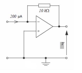
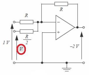
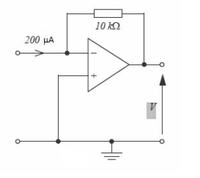
I am struggling to determine the unknown voltage of the Op Amp I have attached.

Could anybody give me any pointers on how to go about solving it?

Thanks


I presume the op-amp is ideal.

To solve the problem just consider:

1. The inputs of the op-amp don't draw any current, so the 200 uA can only flow into the resistor
2. You can apply the virtual ground concept: V+ = V-, that is V- = 0V
 
Thanks for the reply. Would the answer then be V = 0-(10k*200uA)
 

That seems too easy. Is it really that simple?
 

Hi,

there are simulation tools... maybe ask them...

*****
That seems too easy. Is it really that simple?

Do you need more difficult questions? I surely find some ;-)

Klaus
 

Hi,

Beware. Some tools (Wizards) are completely wrong.

Might be...

But if a simulation tool can not solve this simple circuit, then throw it away...

****

On the other hand: If one needs a simulation tool to solve this, then "electronics" may be the wrong job.

Klaus
 

Thanks for your help everyone. I am finding this next one a lot more difficult to understand as I have a mixture of known voltages and unknown resistances.

Any tips on how to solve this one? Thanks in advance


Just apply the two conditions you used to solve the previous problem and add to these the superposition.
So, as before, you know the (ideal) op-amp will set V- = V+ = 0.
 

I'm totally thrown off by the resistors in parallel. Do i treat them as sepearate entities due to a voltage going into each one or do I calculate it based on the resitance added together e.g. 1/Rt=1/R1+1/R2. I am to assume that the virtual earth summing point would be a combination of 1V + unknown V * the resistors? If it is how would I go about working with the 3 unknowns?

Thanks
 

Hi,
this is a tip.


Solve those, then, do what is said in post #11.
 

The negative input of an opamp with negative feedback is a virtual earth. That is its potential is zero volts for the sake of calculations. If you are are purist you could call it .000001 V.
So you work out how the total current flows into the virtual earth. This current has to be supplied by the output. So this current flows through the feedback resistor, back into the virtual earth. This then will give you your Vout.
Frank
 

Thanks for the reply I have the following:

Known input is 1 V. Output is -2V
Since Rf = Ri gain is -1V.
Known input current = 1V/Ri = -1V
The ouput is -2V so the unknown input must be the same as the known.

-2= -(1V+1V)

Unknown voltage = -1V

Any good?
 

No.

I will refer to pictures in post#14.

First schematic of the superposition: Vout1=-2·V (i.e. -2 · Unknown voltage)
Second schematic of the superposticion: Vout2=-1 volts

Sum together: -2 = Vout1 + Vout2 <=> -2= -1 -2·V <=> V=1/2
 

You can see the problem also this way:

Gain relative to the known voltage G1 = -R/R = -1
Gain relative to the unknown voltage G2 = -R/(R/2) = -2

Output voltage will be: G1*1 + G2*V = -2 (superposition) that is:

-1 + (-2)*V = -2 ==> V = 1/2 as found by CataM
 

Status
Not open for further replies.

Similar threads

Part and Inventory Search

Welcome to EDABoard.com

Sponsor

Back
Top