Continue to Site

Welcome to EDAboard.com

Welcome to our site! EDAboard.com is an international Electronics Discussion Forum focused on EDA software, circuits, schematics, books, theory, papers, asic, pld, 8051, DSP, Network, RF, Analog Design, PCB, Service Manuals... and a whole lot more! To participate you need to register. Registration is free. Click here to register now.

[PIC] Power factor measurement using PIC18f4520

Status
Not open for further replies.
Here is the latest code I made. The code inside the
Code:
if(process)
condition is correct because if I substitute some known deltaT and find out the PF value then it gives correct result but as the timer value returned is incorrect I am getting incorrect value for PF.
This is the new project for PF Measurement. It uses betwixt's method but it is not working as expected.

I am displaying time between rising and falling edges of the XOR gate output signal o line 4 of the LCD. It is giving wrong timer value.

The working is like this.

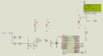
Voltage and current ZCD sifnals are fed to XOR gate and also to INT1 and INT2 pins. INT1 is voltage ZC signal amd INT2 is current ZC signal.

Initially only INT1 and INT2 are enabled and INT0 is disabled.

The measurement is using 2 AC cycles.

In the 1st AC cycle the INT1 and INT2 is used to detect whether voltage appeared first or current. After this is done INT0 is enabled and INT1 and INT2 are disabled.

Now INT0 is used to detect rising edge and when detected the INTEDG0 bit is reversed to detect falling edge and Timer1 is started when falling edge is detected Timer is stopped and INT0 is disabled. and process flas is set.

In main loop it is tested if process flag is set and if it is set then PF value is calculated from the timer value and displayed and then again INT1 and INT2 are enabled for next cycle.


If you need more details regarding the project then please mention it.

I was not able to find the bug in the code. Maybe more experienced programmers can find the bug.

- - - Updated - - -

Edit:

I tried to implement betwixt's first method that is analog method of PF measurement but not getting precise

values.

The working is like this.

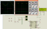
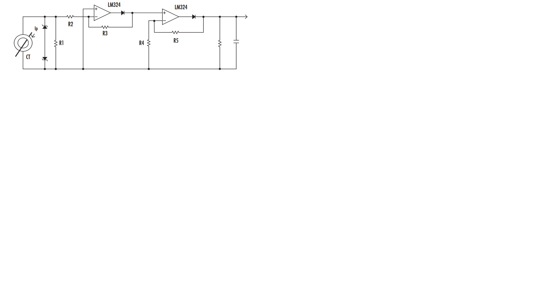
The output of the XOR gate is passed through a low pass filter which gives a voltage. It is fluctuating in

Proteus.

When there is a difference of 52.5 ms (45 degrees) between voltage and current the voltage at the ADC input is

1.17V (fluctuating between 1.16 and 1.17 V).

Lat's take it as 1.17V.

ADC Calculation is like this.

for 1.17V the deltaT should be 2.5 ms

Code:
deltaT = (ADC_Read(2) * 1.0504202e-2 / 1023.0);

For 5V adc input raw adc value is 1023.0. Therefore for 1.17V it will be 239.382

So, deltaT = 239.382 * 1.0504202e-2 / 1023.0

= 0.002457983268 = 2.4579 ms which is approx to 2.5 ms


Angle in decimal degrees is calculated using the formula

Code:
angle_in_decimal_degrees = (deltaT / T) * 360.0;

T = 20 ms (50 Hz)

so, answer is (2.4579 ms / 0.02) * 360.0

= 44.243698824 decimal degrees which is approx to 45 degrees.

This is converted to radians

1 degree = 1.74532925e-2 radians

so,
Code:
angle_in_radians = angle_in_decimal_degrees * 1.74532925e-2;

= 0.77219821685717802

powerFactor = cos(0.77219821685717802) = 0.71637868009896187076245547933012

I have to get 0.707

Where is the mistake ? Is my low pass filter correct ? If not, please provide the correct values for the low

pass filter resistor and capacitor.
 

Attachments

  • Mains Monitor Ver4.rar
    78.4 KB · Views: 86
  • Mains Monitor.png
    Mains Monitor.png
    136.4 KB · Views: 116
  • Mains Monitor Ver5.rar
    87.1 KB · Views: 76
  • Mains Monitor.png
    Mains Monitor.png
    34.2 KB · Views: 102
True power factor is the ratio of real and apparent power, not just the phase displacement angle. There is a good explanation here: https://en.wikipedia.org/wiki/Power_factor

Some riple in the filtered output of the XOR gate is inevitable but you can minimize it by increasing the capacitor value or by averaging several samples.

Brian.
 
Hello all and thank you!

@betwixt, in the circuit you've posted:


1) For the AC voltage measurement, there is no galvanic isolation between mains and PIC. I already have a 230VAC to 12VAC voltage transformer, and a single phase full wave rectifier, that its output is connected to the resistive voltage divider you've drawn.
For R1 and R2 their values can be easily calculated (voltage divider circuit), but what about the resistor value flashed in red? Also what about capacitance value arrowed with a green arrow? [I assume that 1Kohm is for resistor and 10nF ceramic capacitor for the capacitor]

2) For the AC current measurement: the CT ratio is 10A/5mA, and its burden resistor value accompanied within its datasheet should be of 200ohms: with the circuit you've provided there is a problem: for max current, there is a 5mA in the secondary, and with 200ohms, you have a total voltage output of 1V: How can this (maximum attainable) value can be voltage divided?
What about placing instead of 200ohms burden resistor a resistor of 10Kohms, such that when having maximum current you have an output voltage of 50V and that 50V can be resistively voltage divided to have @Y an output of 5V and therefore R3 and R4 can be also calculated. What about the resistor value flashed in red, as well as capacitor value flashed in green [I also assume they're of 1Kohm for the resistor, and 10nF for the ceramic capacitor]
Isn't such circuit needs a linear amplifier (such as LM324) or the total connection must be changed to a precision rectifier?

3) In the XOR circuit: there are no problems except for the red flashed resistor value as well as the green flashed ceramic capacitor. I assume that the black arrows corresponds to neutral nodes.

Awaiting your reply thank you

- - - Updated - - -

Hi,

@KhaledOsmani:
I see you are confused.

Klaus

Hello Klaus, much thanks to you.

For the path to be followed, I say let's go after betwixt method, with the circuit he'd posted:


After solving its complexities (posted a comment about it, of resistor/cap values, as well as other difficulties regarding CT circuit) we start a coding routine, in order to feed the PIC analog pins with equivalent V, I, pf, using mikroC compiler as "universally accepted coding language" that I hope to grasp as much as I can as faster as I can from its essentials (I have other courses to study, midterms, projects)

Thank you dear
 

Hi,

I'd like to recommend a second order LPF for filtering the pf analog signal.
The ripple is frequency is 100Hz.
To target a 1 LSB ripple with a second order filter with about 3Hz.
A simple R-C-R-C solution could be: 2k4 - 22uF - 7k5 - 6.8uF

Klaus
 
Hi,

I'd like to recommend a second order LPF for filtering the pf analog signal.
The ripple is frequency is 100Hz.
To target a 1 LSB ripple with a second order filter with about 3Hz.
A simple R-C-R-C solution could be: 2k4 - 22uF - 7k5 - 6.8uF

Klaus

Hi, thank you

Do you have any replies concerning the CT circuitry?
 

This is new version of the project. The changes in code is that I have multiplied deltaT result with a small factor to get precise time value. Circuit is changed. I have used KlausST's LPF circuit. There is a slight ripple. Don't know if it is Simulation problem or not. I am only testing in Proteus.

For 2.5 ms difference between voltage and current (45 degrees) I am getting 0.706 (it should be 0.707). It can be fine tuned in code if ripple stops.


Edit:

@ betwixt

20% of 220V is 44V

So, AC mains voltage can go upto 264V.

Considering max mains voltage as 264V I am calculating the value of the two resistors R1 and R2 in your circuit.

For R1

264V - 44V = 258.4V

Let's assume current to be 1 mA.

So, R1 = V1 / I = 258.4 / 1 mA = 258400 E = 258.4k

For R2

5.6V / 1 mA = 5.6k

Power dessipated in R1 = IIR1 = 1 mA * 1 mA * 258.4k = 0.2584 W = 258.4 mW

and in R2 =

5600 * 1 mA * 1 mA = 5.6 mW

So, Can OP use these values for R1 and R2 and use a 1/2W resistor for R1 ?

- - - Updated - - -

ACS712 sensor for Irms measurement.

https://www.sunrom.com/m/4496
 

Attachments

  • Mains Monitor Ver7.rar
    92.1 KB · Views: 71
  • Mains Monitor.png
    Mains Monitor.png
    22.5 KB · Views: 101
Last edited:

Hi,

Do you have any replies concerning the CT circuitry
It will be hard to find out the true current:
Because of the two diodes it will be nonlinear. And it uses averaging.
For power calculation you need RMS values. To calculate /estimate the RMS current from the ADC values you will need a table.
And it is limited to pure sine shape.
The output value is somewhere inbetween averaged_half_bridge_rectified_value and peak_value...depending on resistor values.

If the diode is connected in series with R3 you will see less error with low currents and you safe one resistor.

*******
In short: it will work. For precise measurement it needs some software effort.

Klaus
 
I can't view the simulation schematic but I assume the diodes are the V and I rectifiers. Klaus is correct that there will be some non-linearity, especially at low readings but I tried to overcome that to some degree by suggesting a slightly higher voltage (5.6V) at the resistor junction than the maximum 5V the ADC can utilize. It isn't a complete cure but it goes some way. The principle is that this is an AC line monitor so it is reasonable to expect a fairly good sine wave input and therefore the peak will be 1.414 times the RMS value in both cases. As the peak and RMS are proportional, the peak which is easier to measure can be used to calculate the RMS. If greater accuracy is needed, the alternatives are to rectify the AC first then reduce it with the potential divider (this needs higher voltage capacitors and resistors though) or to use a precision rectifier circuit but that needs more components.

Brian.

Thank you Brian!

All the analog circuit you've provided will work great (no need to be accurate 100%) but the whole CT circuit is a problem, and will NOT work IF referred to CT datasheet:

The burden is 200ohms, so for max load current the secondary would be a 5mA, that gives a secondary voltage of 0.005*200= 1V << this cannot be held at your voltage divider/filter circuit.

May help at this stage be only about CT circuitry.

Can I branch at CT circuitry a burden of 10Kohms or 1Mohm such that your circuit can be applied somehow, but
I won't be able to supply higher than 1A load?

Or should I post a precision rectifier circuit and you help me building it by giving its R/C parameters?

PLEASE at this stage the only help I'll benefit is constructing the CT circuitry with a 10A/5mA CT.


Thanks

- - - Updated - - -

Hello,

Trying to consider the following CT circuit:


CT: 10A/5mA
R1 = 200 ohms
R2 = R3 = 2Kohms
R5/R4 + 1 is the gain of the second stage (should be considered after testing first step voltage, and how much I would like to amplify it.
RC Circuit: C=3.2uF and R=382Kohms


Suggestions please [at this phase I`m only concerned about designed proper Vadc circuit which is already done, Iadc circuit, and the XOR circuit is nothing but taking two inputs from both adc circuits and fed to PIC]

Later on we will discuss code (C code)

Thanks
 

Sorry (again) too many people are asking me to do too many things at the same time...

I still can't see an up to date schematic but if I understand, you have a transformer based power supply to produce the 5V for the circuit. I assume 5V it is regulated from the rectified 12V transformer output. As the transformer output voltage is roughly proportional to its input voltage and you are rectifying it anyway, you can sense the AC line voltage by dividing down the DC before the 5V regulator.

Example, with 220V line AC you get 12V AC from the transformer, that is about 17V peak minus two diode drops (assuming you use a bridge rectifier giving ~15.5V DC at the regulator input. If you divide that with a series 2.7K resistor and 1K to ground it will drop 15V down to 4V which you can then feed directly to the ADC. With VDD as the ADC refererence you get an ADC value of 828 decimal (0x33C hex) representing 4V and a good safety margin. There is no point in using a precision rectifier for the voltage circuit as any non-linearity will be at low voltages and I think it's safe to assume you would only use this if there was sufficient line voltage to power it anyway!

For the CT, you can increase the value of the burden resistor (within reason) to make it give more V out in the secondary per Amp in the primary. You can set the value so your anticipated maximum load current gives ~5V out. The important thing to consider if you do that is the possibility of an overload making the secondary voltage dangerously high but a series resistor and Zener diode should be sufficient to protect the ADC input.

If you want to use the precision rectifier method instead, you ideally need two op-amp stages (one dual op-amp IC) with the first having a diode in the feedback loop and the second being a simple voltage amplifier. The idea is you compensate the drop in the rectifier diode with an equal and opposite drop in the feedback diode so they should be the same type for best matching. Be careful with the op-amp power supply, you may need to use both positive and negative supply rails to maintain accuracy close to 0V output.

Brian.
 
Hi,

I tried to develop a circuit for current measurement.
This is the result:
PRAC.png
Because the burden is after the rectifier.. this should increase linearity. The diode voltage drop is not involved in the output signal.
The full bridge rectifier generates twice the mains frequency. 50Hz --> 100Hz.
Then the same 2nd order low pass filter as with the XOR output. --> ripple should be max 1 LSB.

For sure at low currents there will be errors depending on the CT´s voltage output capabilities.

The result is not as good as with true RMS. But for a sine input the output should be very predictable.

The effort is not too much I think. Any small rectifier will do. Or use two BAT54S.
Maybe you could do some tests with known load currents.

Hope this helps

Klaus

- - - Updated - - -

Update:

I just "copied" the circuit for voltage measurement:
RAV.png
In the simulation a 12V AC input gives 2.82V DC output voltage
Increasing input to 120% gives 121.05% output voltage.
Decreasing input to 80% gives 78.96% output voltage.

This is a true average of the rectified value. This is more noise immune than a "peak" detection circuit. And it is more immune to errors casued by the (usually) flatened top of the mains sine.
Simulation shows a ripple of about 4mV wich is below 1 LSB at 5V range and 10 bit ADC.

Klaus
 
@ KlausSt

How you said frequency of output of XOR gate is 100 Hz ? It occurs once every 20 ms. Isn't the frequency 50 Hz ?

Please provide the exact algorithm for using software to calculate apparent power and true power and find out PF from it. I have never done such a thing.

I know how to use timer interrupts and also call ADC function in timer ISR to take samples. I want to know what value timer interrupt has to be generated to take samples and how many samples have to be taken and also provide the complete math method.

Should I also use a ZCD circuit for detecting ZC and start taking adc samples when ZC is detected. Please this will be easier for me to implement if you explain the method in detail and stepwise.

Please let's help the OP in completing the project.
 
Last edited:
Hi,

How you said frequency of output of XOR gate is 100 Hz ? It occurs once every 20 ms. Isn't the frequency 50 Hz ?

From your simulation:
XOR_wf.png

Klaus
 

Yes, you are correct. I didn't see it. It is also showing a pulse at 0 and 180 degrees. Please reply to other things I asked.
 

Hi,

you mean to calculate apparent power and so on from your post#173?

--> I think the OP decided not to use my solution. Am I wrong?

Klaus
 
Yes, that post. I will tell OP to use your method because you said it will give precise results. Using Timer interrupts to take samples is not a problem for me. The PIC is running at 20 MHz and so more samples can be taken.

Tell me when to start taking samples and when to stop and how many samples to take. Also provide the circuit for such measurement. I think the AC has to be dropped to 2.5V and a DC of 2.5V has to be added to it to shift it to 0 to 5V and input it to PIC ADC for measurement. Also tell all the maths involved in calculating the apparent power and true power.

I will use floating point calculations. I think PIC can do it.
 

Hi,

you mean to calculate apparent power and so on from your post#173?

--> I think the OP decided not to use my solution. Am I wrong?

Klaus

Hello,

Thank you for all circuits. I will try them all.

I will feed both three channels of V and I and the output of the XOR circuit to three analog PIC inputs. This was not your method?!
 

@Khaled Osmani

XOR method is brian's method. KlausST's method was calculating apparent and true powers and then calculate PF from them.
 

Sorry (again) too many people are asking me to do too many things at the same time...
Brian.


I`m very thankful, and more sorry for overwhelming you with questions repeatedly.

I still can't see an up to date schematic but if I understand, you have a transformer based power supply to produce the 5V for the circuit. I assume 5V it is regulated from the rectified 12V transformer output. As the transformer output voltage is roughly proportional to its input voltage and you are rectifying it anyway, you can sense the AC line voltage by dividing down the DC before the 5V regulator.


Yes, 100%. This is what I've done, a voltage divider with a filtering capacitor of 10uF, that outputs maximum of 4V and fed into PIC PORTA.0


Example, with 220V line AC you get 12V AC from the transformer, that is about 17V peak minus two diode drops (assuming you use a bridge rectifier giving ~15.5V DC at the regulator input. If you divide that with a series 2.7K resistor and 1K to ground it will drop 15V down to 4V which you can then feed directly to the ADC. With VDD as the ADC refererence you get an ADC value of 828 decimal (0x33C hex) representing 4V and a good safety margin. There is no point in using a precision rectifier for the voltage circuit as any non-linearity will be at low voltages and I think it's safe to assume you would only use this if there was sufficient line voltage to power it anyway!

Yes, all cool with that.

For the CT, you can increase the value of the burden resistor (within reason) to make it give more V out in the secondary per Amp in the primary. You can set the value so your anticipated maximum load current gives ~5V out. The important thing to consider if you do that is the possibility of an overload making the secondary voltage dangerously high but a series resistor and Zener diode should be sufficient to protect the ADC input.

Ok, so my anticipated load is of 8Amps as a maximum load.
from CT ratio: output current is 8/2000 = 0.004
For a burden of 10Kohms the output resultant voltage is 40V. This 40V can easily be voltage divided.
What are the values of the Resistor (other than the ground voltage dividing one) that helps protecting with help of Zener diode, that helps in protecting the ADC input in case of overloading?

Thank you

- - - Updated - - -

@Khaled Osmani

XOR method is brian's method. KlausST's method was calculating apparent and true powers and then calculate PF from them.

Dear Jayanth,

In your professional C coding, what method have you used? When I see your attachment I see a XOR circuit (in proteus simulation).
 

Hi,

This was not your method?!
No.
My preferred solution is to feed both AC signals I and U directely without rectifier and without filtering to the ADC. Nothing else. No XOR.

Inbetween i thought the digital pulse witdh measurement caused problems..and just remembered this alternatively could be done with an ADC.
...many ways...many solutions..maybe causes confusion...sorry.

Klaus
 

Status
Not open for further replies.

Part and Inventory Search

Welcome to EDABoard.com

Sponsor

Back
Top