Continue to Site

Welcome to EDAboard.com

Welcome to our site! EDAboard.com is an international Electronics Discussion Forum focused on EDA software, circuits, schematics, books, theory, papers, asic, pld, 8051, DSP, Network, RF, Analog Design, PCB, Service Manuals... and a whole lot more! To participate you need to register. Registration is free. Click here to register now.

Why my topology of rat-race mixer does not work?

Status
Not open for further replies.

Terminator3

Advanced Member level 3
Joined
Feb 25, 2012
Messages
802
Helped
71
Reputation
142
Reaction score
63
Trophy points
1,308
Activity points
9,027
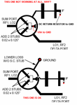
Below is the image that explains my question:
ratrace-3.png
As you can see, instead of taking IF from the point where diode pair is connected, i take IF from high impedance line that was connected to GND before. DC return is identical, but reversed in position. Unfortunately that does not work and i can't understand why. It is totally silence on the IF output. Although i thought it must be possible, because similar mixers exist:
(TYPE 1)
ratrace-2.png
But on this images separate diodes are used. But i still can't understand why using single-case diode pair can stop mixer from working in my setup?

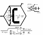
Here is more traditional rat-race mixers:
(TYPE 2)
ratrace-1.png
So all i wanted is to use TYPE 1 arrangement but use diode pair in single case.

I checked my mixer by cutting traces, and when i come back to TYPE 2 configuration it starts to work. I am confused what is the problem here.

I taken images from:
1. Agilent EEsof EDA "The 2001 CAD Benchmark Rat-Race mixer characterisation"
2. SMS7630-061: Surface Mount, 0201 Zero Bias Silicon Schottky Detector Diode data sheet
3. Low Cost Mixer for the 10.7 to 12.8 GHz Direct Broadcast Satellite Market (application note 1136)
4. https://www.qsl.net/yo4hfu/Files/TG/RAT RACE 1296 mixer.pdf (rat-race mixer by WA6UAM H.Paul Shuch)
5. https://lsedr.weebly.com/rf-mixer--mezcladores-de-rf.html (rat-race mixer)
 

Below is the image that explains my question:
View attachment 119300
As you can see, instead of taking IF from the point where diode pair is connected, i take IF from high impedance line that was connected to GND before. DC return is identical, but reversed in position. Unfortunately that does not work and i can't understand why. It is totally silence on the IF output. Although i thought it must be possible, because similar mixers exist:
(TYPE 1)
View attachment 119299
But on this images separate diodes are used. But i still can't understand why using single-case diode pair can stop mixer from working in my setup?

Here is more traditional rat-race mixers:
(TYPE 2)
View attachment 119298
So all i wanted is to use TYPE 1 arrangement but use diode pair in single case.

I checked my mixer by cutting traces, and when i come back to TYPE 2 configuration it starts to work. I am confused what is the problem here.

I taken images from:
1. Agilent EEsof EDA "The 2001 CAD Benchmark Rat-Race mixer characterisation"
2. SMS7630-061: Surface Mount, 0201 Zero Bias Silicon Schottky Detector Diode data sheet
3. Low Cost Mixer for the 10.7 to 12.8 GHz Direct Broadcast Satellite Market (application note 1136)
4. https://www.qsl.net/yo4hfu/Files/TG/RAT RACE 1296 mixer.pdf (rat-race mixer by WA6UAM H.Paul Shuch)
5. https://lsedr.weebly.com/rf-mixer--mezcladores-de-rf.html (rat-race mixer)
You probably need anti-series diodes in one case and series diodes in the other.
 
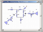
I see direction of your idea. Not sure problem is here. At least there must be some output from mixer if one of diodes placed wrong. I reviewed https://literature.cdn.keysight.com/litweb/pdf/5989-8896EN.pdf again and on theirs schematic diodes are still in series:
ratrace-4.png
The only difference from this schematic is that diodes placed inside ring, and use one common microstrip structure with stub and via: TL2, TL8, TL9 and via to GND removed, and second diode D2 connected to first microstrip structure. I think problem may be with common VIA to GND, so current flows not ass supposed to. I will try separate vias to GND and stubs, as shown on schematic. and then try to short them to see if the problem is because of that.
 

I see direction of your idea. Not sure problem is here. At least there must be some output from mixer if one of diodes placed wrong. I reviewed https://literature.cdn.keysight.com/litweb/pdf/5989-8896EN.pdf again and on theirs schematic diodes are still in series:
View attachment 119501
The only difference from this schematic is that diodes placed inside ring, and use one common microstrip structure with stub and via: TL2, TL8, TL9 and via to GND removed, and second diode D2 connected to first microstrip structure. I think problem may be with common VIA to GND, so current flows not ass supposed to. I will try separate vias to GND and stubs, as shown on schematic. and then try to short them to see if the problem is because of that.

Okay lets analyze the Ratrace with ideal diodes (on=0 Ohms and off=open). The Ratrace is 1.5 wavelengths (540 degrees) in circumference.

RF and LO assumed to be very close to the design frequency of the Ratrace.

Case 2 (the lower working circuit):
1. The LO provides antiphase drive to the diode ports, which for series diodes, switches them on and off every cycle. Diode port Tlines are assumed to be identical. The antiphase of the LO also cancels at the RF port which provides isolation.
2. The driven diodes act as a sampling switch every half cycle and is in series with the IF port; so the RF is rectified thru two parallel equal length paths.

Case 1 (the upper non-working circuit):
1. Most of the previous description applies except that this time the diodes must provide shunt shorts and opens to the RF path every cycle to rectify. But, what screws it up is that the parallel paths are 180 degrees out of phase for the RF parallel paths (to the IF port) which results in a virtual short of the rectified RF signal.

Solution: try moving the IF port so that the RF paths are equal. Note: the IF should look open to the LO.
 
Status
Not open for further replies.

Part and Inventory Search

Welcome to EDABoard.com

Sponsor

Back
Top