KhaledOsmani
Full Member level 6

Hi
I want to make a simple project for the landline communication company that I'm working for:
Here in this country landlines are analog system based where the line is originated from an OCB to a main distribution frame to an access point and finally to the customer.
This is all wired up underground with twisted pairs.
Due to the nature of this system, many problems different occurs , and as a maintenance staff I want to design a PIC project to test the state of the line when a problem occurs; the routine in the company is to test the efficiency of the line with a simple handy phone if there is a line or if it is open circuited, but sometimes the line is occuring perturbances and it is neither shorted nor open circuited, so the customer nags from unability to hear the conversation.
There is a DC voltage for each state of error:
1) if the line is well functioning the DC voltage across the two terminals of the line pairs is X volts
2) if the line is under shortcircuit there is a 0V
3) if the line is having electromagnetic interferences or any type of noise the voltage would be Y volts
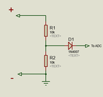
What I wan tto make is a PIC circuit with an LCD and two probes to connect the line terminals across it, and make a voltage divider circuit then process it to ADC and enter it to the PIC; here a subfunction would take place, if voltage > < = to a certain value place a message accordingly to the LcD to inform the staff that the line situation is of this type or that type or whatever.
1) what is the maximum voltage input that the PIC could handle?
2) how to make a protection for the PiC of the line is mistakenly having an AC phase merged into it
3) after the voltage divider circuit how to place two terminals that on which the two terminals of the line would be connected to? Assume the + terminal is connected to portA0 the other ground terminal where should take place? To the ground of the 5V PIC supply??


