Continue to Site

Welcome to EDAboard.com

Welcome to our site! EDAboard.com is an international Electronics Discussion Forum focused on EDA software, circuits, schematics, books, theory, papers, asic, pld, 8051, DSP, Network, RF, Analog Design, PCB, Service Manuals... and a whole lot more! To participate you need to register. Registration is free. Click here to register now.

Voltage divider ADc input to PiC18f4520

Status
Not open for further replies.

KhaledOsmani

Full Member level 6
Joined
May 4, 2014
Messages
384
Helped
1
Reputation
2
Reaction score
1
Trophy points
18
Activity points
3,933
Hi

I want to make a simple project for the landline communication company that I'm working for:

Here in this country landlines are analog system based where the line is originated from an OCB to a main distribution frame to an access point and finally to the customer.

This is all wired up underground with twisted pairs.

Due to the nature of this system, many problems different occurs , and as a maintenance staff I want to design a PIC project to test the state of the line when a problem occurs; the routine in the company is to test the efficiency of the line with a simple handy phone if there is a line or if it is open circuited, but sometimes the line is occuring perturbances and it is neither shorted nor open circuited, so the customer nags from unability to hear the conversation.

There is a DC voltage for each state of error:
1) if the line is well functioning the DC voltage across the two terminals of the line pairs is X volts
2) if the line is under shortcircuit there is a 0V
3) if the line is having electromagnetic interferences or any type of noise the voltage would be Y volts

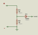
What I wan tto make is a PIC circuit with an LCD and two probes to connect the line terminals across it, and make a voltage divider circuit then process it to ADC and enter it to the PIC; here a subfunction would take place, if voltage > < = to a certain value place a message accordingly to the LcD to inform the staff that the line situation is of this type or that type or whatever.

1) what is the maximum voltage input that the PIC could handle?
2) how to make a protection for the PiC of the line is mistakenly having an AC phase merged into it
3) after the voltage divider circuit how to place two terminals that on which the two terminals of the line would be connected to? Assume the + terminal is connected to portA0 the other ground terminal where should take place? To the ground of the 5V PIC supply??
 

1) what is the maximum voltage input that the PIC could handle?

PICs ADC can handle max 5V DC.

2) how to make a protection for the PiC of the line is mistakenly having an AC phase merged into it

Make a voltage divider so that the voltage across bottom resistor doesn't exceed say 5V (to be safe make it 4.7V) Take the voltage across this resistor and add a series diode. 0.7V drop across diode and so in calculation add 0.7V. This will protect ADC from inputting AC. The AC magnitude is assumed to be of 5 or less volts.

3) after the voltage divider circuit how to place two terminals that on which the two terminals of the line would be connected to? Assume the + terminal is connected to portA0 the other ground terminal where should take place? To the ground of the 5V PIC supply??

There will be two resistors in the voltage divider and if the bottom resistor gives max 5V for ADC then take voltage across this resistor. The point between the two resistors is + and the other end of the bottom resistor is - (connected to circuit GND).

In the image you have to calculate the resistor values based on your max and min voltage input.
 

Attachments

  • adc input.png
    adc input.png
    4.4 KB · Views: 115
Last edited:
@milan.rajik

Thank you.
In the last question that I had asked, i know the terminals of the 5V but the question was about where to connect them according with the PiC circuit? How to give the PIC +Vcc and -Vcc assuming that Vccmax = 5v then to make ADC and display o ln screen, WHERE to branch the two termials??
 

-Vcc is not given to PIC. PIC has VCC and GND. They are PIC's power supply pins. + and - in above image is for probes. To ADC goes to ADC pin like AN0. That's all.
 
It is likely that your phone line is the same as ours. You get 50VDC when the phone isn't used 12VDC when you engage and 80VAC when it rings.
Because you don't know how the line will be connected by the engineer, either positive or negative 50VDC, you have to use a bridge rectifier that will give the PIC positive voltage no matter how connected to the line. The 10uF will filter the 80VAC from the ring. The 100K and 10K will attenuate the 50VDC to 5VDC. The diode is an extra protection for the PIC input.
https://obrazki.elektroda.pl/6294533100_1430001685.gif
 
Last edited:
@VBase

Thank you, you made extra explanations, but I dont get what you mean by PIC 5V in the schematic that you have attached.
Comparing with what @milan.rajik said and thankfully attached, there only must be a single input to the PIC to make the comparision and outputs the case on the LCD, which is the analog input (single wire to PORTA pin 0 for example).

But What is 5V PIC input meant for? and how can you relate your image with @milan.rajik one?

by the way, do you advice me buying Microchip ICD3? will its mplab version be compatible with windows8? is it the best software/hardware solution to program a PIC? otherwise please tell me your opinions

I corrected the drawing do make it clearer.
Vcc is the 5V supply to the PIC and the LCD, you can use a battery for that.
Vee is the ground of the PIC.
Input is the analogue input of the PIC.

I think the advice Milan gave you about PicKit3 is a good advice.
My experience with microcontrollers is very limited, I use MPLAB and MPLAb X and I know that they work on win 8. Writing code for LCD will be easier using MicroC which is free to download.
There are many threads in this forum about what software and hardware to use.
Milan can give you better advices than I.
After you have everything you can ask the forum for help with your program.

https://obrazki.elektroda.pl/7584779700_1430154913.gif
 
@Vbase

Im using an ac supply with a 7805 regulator for PIC power as well as LCD.

I dont want to feed the PIC from the line voltage so there would be inly one output (analog input to the pic) to be used from your schematic right? Same as Milan picture but with bridge rectifier to ensure only DC output only.

Consider the + of the line and - of the line is a system of itself, enhanced with the bridge rectifier, we agreed to only output the analog to PIC as input, the ground of this system (outputed from the bottom resistor) must be connected to PIC GND wether the pic is fed from the line or else from the regulator? Or is it only must be connected in case where i apply your schematic as it is and feed the pic from line voltage??

As for the programmer, i used to use ICD2.

I want to upgrade and i have never used a pickit before, i will surely use it much and program large boards with different pic and sensors, do you still insist to buy a pickit? Is that choice is money-wise only?

Thanks
 

You have to connect the line as the circuit shows and you also have to supply 5V from the LM7805. The line doesn't power the PIC, it only gives voltage for the PIC to measure.

If you are happy with ICD2 then you don't need to get PicKit.
Have fun with your project.
 
Hello,

please find attached the circuit diagram.
You are only concerned with the green schematic if true or false.
thank you
 

Attachments

  • IMG_4010.JPG
    IMG_4010.JPG
    1.9 MB · Views: 121

Hi,

Thanks for your time.
The corrected schematic that you assumpted would harm the pic bu giving it 10volts instead of 5.

You are connecting the output of the bridge system to the +Vdd Vss of the pic parallely with the 5V already got from the 7805.

Why are you insisting to connect the + and - terminals of the line (surely after being bridged and voltage divided) to the + and - of the pic??

The analog output of the bridge connected to porta.0 and gnd of it (bridge) connected to gnd of pic arent a sufficient criteria to have a volt meter reading of the line through the pic?? Please see the initial schematic that milan.rajik had attached and tell the difference between it and yours.

Thanks
 

The circuit I gave you has nothing to do with milan's circuit. Read post #5 how it works.
If you have doubts in it don't use it.
 

I had tried your circuit, it outputs 2,69 volts at adc input (due to diodes break down voltages) the funny thing that got me spooky is that when switching the voltmeter to Ac volts, the output should be zero because all ac if existed are rectified to dc, but it outputs 4,5V AC!!!!!!

I disconnected the modem as well as the landline phones and took the initial phone line to test its voltage during steady state (no call no hang on) it outputs 54,5 V DC in the same time 117 V AC !!!!! What the hell is this? How come two sorts of voltage at the same time?

Plus i tried to put load on the line, for example a buzzer: it worked, a small red led: it worked, a 12v dc relay: it worked, a 24v dc relay: it worked, the line works as an excellent auto dc power supply!!!!

For god sake any explanations????
 

Status
Not open for further replies.

Similar threads

Part and Inventory Search

Welcome to EDABoard.com

Sponsor

Back
Top