Continue to Site

Welcome to EDAboard.com

Welcome to our site! EDAboard.com is an international Electronics Discussion Forum focused on EDA software, circuits, schematics, books, theory, papers, asic, pld, 8051, DSP, Network, RF, Analog Design, PCB, Service Manuals... and a whole lot more! To participate you need to register. Registration is free. Click here to register now.

74hc595 16f877a interfacing problems

Status
Not open for further replies.

varunme

Advanced Member level 3
Joined
Aug 10, 2011
Messages
741
Helped
17
Reputation
36
Reaction score
17
Trophy points
1,318
Activity points
5,764
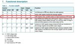
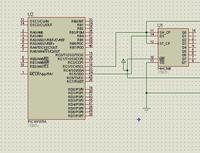
I tried to interface 74hc595 with 16f877a, but without connecting the pic also, the output leds to the 595 is always on, the connection diagram is as below

what can be the problem?


when i touch the ic legs with multimeter probe, irregular on and off of the leds are observed


like the video below

 
Last edited:

Regarding the interference, welcome to the imperfections of flip flops.

We know that all mosfets have some input gate to drain capacitance and after experience we know that flip flops need to be buffered if going onto busses or long wires. The HC595 has a buffer on each output even pin 9 with is QH' or the only output inverted. which may be more sensitive to output injected transients getting feedback to input.

Injecting a charge from the probe capacitance at 5Vcan actually inject a glitch internal to the IC and cause a state change.
hc595.jpg
 
  • Like
Reactions: varunme

    varunme

    Points: 2
    Helpful Answer Positive Rating
That capacitor has to be connected between QH' and which pin?
 

- The circuit shown in post #1 makes no sense. To control HC595, you need at least 3 processors signals: bitclock, data and frameclock. Review known working 595 output circuits.

- It normal that HC595 has accidental output register state before it's explicitely loaded with data. Special designed circuits use HC595 output enable or HC594 with output register reset function to enforce inactive power-on state.

- Unwanted switching of HC595 outputs can occur if the driving processor lines aren't yet initialized or otherwise driven incorrectly. Also if your circuit lacks sufficient power supply filtering.
 
  • Like
Reactions: varunme

    varunme

    Points: 2
    Helpful Answer Positive Rating
I shorted the shift clock and latch clock, so it uses only two pins
it works in proteus, but in real hardware, not

i added 1uf in QH' to gnd, same result
 

Is your PIC ok ? Have you enable MCLR ? If yes, have you pulled up MCLR pin using a 10k ? Show your exact hardware circuit.
 

PIC i am using a dev board.

- - - Updated - - -

The pic is working properly since, i tested led blinking another port pin simeltaneously, and its working
 

I shorted the shift clock and latch clock, so it uses only two pins
it works in proteus, but in real hardware, not

i added 1uf in QH' to gnd, same result

You don't have to add external cap here ... Sunnyskyguy was explaining about inherent capacitance that exists internal to MOSFET structure in IC.

Is there a need to short the two clocks? Can't they be separated and used as required?

In your condition, it looks like the power up output control of 595 IC is not taken care. Instead of connecting the OE# to GND control it from micro. Look at the functional diagram of 74hc595 ic and try to follow it. Attached if the image of this functional table.
 

Attachments

  • 74HC595.JPG
    74HC595.JPG
    108.3 KB · Views: 63
  • Like
Reactions: varunme

    varunme

    Points: 2
    Helpful Answer Positive Rating
I shorted the shift clock and latch clock, so it uses only two pins it works in proteus.
It "works" in a way that all output pins get same data...
 
  • Like
Reactions: varunme

    varunme

    Points: 2
    Helpful Answer Positive Rating
Here is the code

Code:
sbit  SR_Latch  at RC1_bit;                 
//sbit  SR_Enable at RC2_bit;                   
sbit  SR_Latch_Direction  at TRISC1_bit;
//sbit  SR_Enable_Direction at TRISC2_bit;


void main() {
           trisc=0;
           trisD=0;
          portc=0;
          portd=0;


SPI1_Init();

while(1) {
long a=0b00000001000001000000000000000111;
//SPI1_Write(0b00000001);
//SPI1_Write(a>>24);
SPI1_Write(a>>16);
SPI1_Write(a>>8);
SPI1_Write(a);
SR_Latch = 1;
PORTC.F0=1;
PORTD.F2=0;
delay_ms(1000);
SR_Latch = 0;
PORTC.F0=0;
PORTD.F2=0;
           a=0b11110000000000000000000000000000;
//SPI1_Write(0b00001000);
//a=~a;

//SPI1_Write(a>>24);
SPI1_Write(a>>16);
SPI1_Write(a>>8);
SPI1_Write(a);
SR_Latch = 1;
PORTC.F0=1;
PORTD.F2=1;
delay_ms(1000);
SR_Latch = 0;
PORTC.F0=0;
PORTC.F2=0;


}
}

- - - Updated - - -

If i touch the ground of the circuit, the leds lights up randomly and when the latch is cleared, all the lights goes off
 

That capacitor has to be connected between QH' and which pin?

YOu have a susceptibility issue with discharging the DMM or wire capacitance to Qh'. adding a cap wont help as you merely induce a ground shift and with your layout issues, problems will arise. Fix the immunity issue with a good layout, twisted pairs to any longish wires., decouple supply close to chips.

The small cap internal to chip is inherent to all CMOS and MOSFETs. WHich is why FF's and registers must be buffered going on a bus with switched loads.
 

DDRCis Data Direction Register. It is like TRISx in PIC. DDRx is for AVR MCUs.


mikroC Code. I have not tested the code. SH_CP and ST_CP are not tied together.


Code C - [expand]
1
2
3
4
5
6
7
8
9
10
11
12
13
14
15
16
17
18
19
20
21
22
23
24
25
26
27
28
29
30
31
32
33
34
35
36
37
38
39
40
41
42
43
44
45
46
47
48
49
50
51
52
53
54
55
56
57
58
59
60
61
62
63
64
65
66
67
68
69
70
71
#define Lo(param) ((char *)&param)[0]
#define Hi(param) ((char *)&param)[1]
#define Higher(param) ((char *)&param)[2]
#define Highest(param) ((char *)&param)[3]
 
sbit SH_CP at RC3_bit;
sbit SH_CP_Direction at TRISC3_bit;
 
sbit ST_CP at RC4_bit;
sbit ST_CP_Direction at TRISC4_bit;
 
sbit DS at RC5_bit;
sbit DS_Direction at TRISC5_bit;
 
unsigned long s_data = 0xAA55;
 
void SPI_Send(unsigned char s) {
 
     unsigned char mask = 0x80;
     char i = 0;
     
     for(i = 0; i < 8; i++, mask >> 1) {
           if(s & mask) 
               DS = 1;          
           else 
               DS = 0;
               
           SH_CP = 1;
           Delay_ms(2);
           SH_CP = 0;              
     }
     
     ST_CP = 1;
     Delay_ms(2);
     ST_CP = 0;
}
 
void main() {
 
     TRISA = 0xC0;
     TRISB = 0x00;
     TRISC = 0x00;
     TRISD = 0x00;
     
     PORTA = 0x00;
     PORTB = 0x00;
     PORTC = 0x00;
     PORTD = 0x00;
     
     SH_CP_Direction = 0;    
     SH_CP = 0;     
 
     ST_CP_Direction = 0;    
     ST_CP = 0;
     
     DS_Direction = 0;
     DS = 0;    
     
     while(1) {
     
           SPI_Send(Highest(s_data));
           Delay_ms(2000);
           SPI_Send(Higher(s_data));
           Delay_ms(2000);
           SPI_Send(Hi(s_data));
           Delay_ms(2000);
           SPI_Send(Lo(s_data));
           Delay_ms(2000);          
     
     }
}

 
  • Like
Reactions: varunme

    varunme

    Points: 2
    Helpful Answer Positive Rating
My aim to send a specific binary to the 595, which is selected with switch case, how can i make it possible?
The data is sent from uart terminal;
 

What are you receiving through uart ? char, int, long, ascii ? You have to use Serial ISR to receive data into a var and test this var in switch statement and do what is required. Don't forget to put breaks in cases of switch.
 
  • Like
Reactions: varunme

    varunme

    Points: 2
    Helpful Answer Positive Rating
from uart, receiving char.
But I dont have an idea to shift it into the 595, thats why I am confused,

I have similar kind of task

Code:
switch(uart_rd){
                      case1: x=0b000011100011001;
                      case2: x=0b000011100011001;
                      casea: x=0b000011100011001;
                      caseb: x=0b000011100011001;

where x has to be shifted into the 595;
 

Try this in hardware. Don't try in Proteus.


Code C - [expand]
1
2
3
4
5
6
7
8
9
10
11
12
13
14
15
16
17
18
19
20
21
22
23
24
25
26
27
28
29
30
31
32
33
34
35
36
37
38
39
40
41
42
43
44
45
46
47
48
49
50
51
52
53
54
55
56
57
58
59
60
61
62
63
64
65
66
67
68
69
70
71
72
73
74
75
76
77
78
79
80
81
82
83
84
85
86
87
88
89
90
91
92
93
94
95
96
97
98
99
100
101
102
103
104
105
106
107
108
109
110
111
112
#define Lo(param) ((char *)&param)[0]
#define Hi(param) ((char *)&param)[1]
#define Higher(param) ((char *)&param)[2]
#define Highest(param) ((char *)&param)[3]
 
sbit SH_CP at RC3_bit;
sbit SH_CP_Direction at TRISC3_bit;
 
sbit ST_CP at RC4_bit;
sbit ST_CP_Direction at TRISC4_bit;
 
sbit DS at RC5_bit;
sbit DS_Direction at TRISC5_bit;
 
char uart_rd = 0, i = 0, j = 0;
char sequence[12] = {0b11000011, 0b11011011, 0b11100011,
                     0b11000011, 0b11111011, 0b11100011,
                     0b11000011, 0b11011011, 0b11100011,
                     0b11010011, 0b11011011, 0b11110011}; 
 
void interrupt() {
     if(RCIF_bit) {
           if(OERR_bit) {
                CREN_bit = 0;
                CREN_bit = 1;
                
                OERR_bit = 0;           
           }
           
           uart_rd = UART1_Read();
           
           RCIF_bit = 0;     
     }
}
 
void SPI_Send(char s) {
 
     char mask = 0x80;
     char i = 0;
     
     for(i = 0; i < 8; i++, mask >> 1) {
           if(s & mask) 
               DS = 1;          
           else 
               DS = 0;
               
           SH_CP = 1;
           Delay_ms(2);
           SH_CP = 0;              
     }
     
     ST_CP = 1;
     Delay_ms(2);
     ST_CP = 0;
}
 
void main() {
 
     TRISA = 0xC0;
     TRISB = 0x00;
     TRISC = 0x00;
     TRISD = 0x00;
     
     PORTA = 0x00;
     PORTB = 0x00;
     PORTC = 0x00;
     PORTD = 0x00;
     
     SH_CP_Direction = 0;    
     SH_CP = 0;     
 
     ST_CP_Direction = 0;    
     ST_CP = 0;
     
     DS_Direction = 0;
     DS = 0;    
     
     UART1_Init(9615);
     Delay_ms(200);
     UART1_Write_Text("Send a byte\r\n");
     UART1_Write_Text("--------------\r\n\r\n");
     
     RCIE_bit = 1;
     PEIE_bit = 1;;
     GIE_bit = 1;     
     
     while(1) {
                
           switch(uart_rd) {
           
                case '0':
                       i = 0;                   
                       break; 
                case '1':
                       i = 3;                      
                       break;
                case '2':
                       i = 6;                      
                       break; 
                case '3':
                       i = 9;                      
                       break;            
           };
           
           if(uart_rd) {           
               for(j = i; j = (i + 3); j++) {           
                     SPI_Send(sequence[j]);
                     Delay_ms(2000);          
               }           
           }     
     }
}

 
  • Like
Reactions: varunme

    varunme

    Points: 2
    Helpful Answer Positive Rating
When tried this code, all the leds in 595 are always on, when sending different values through uart
 

Status
Not open for further replies.

Similar threads

Part and Inventory Search

Welcome to EDABoard.com

Sponsor

Back
Top