Continue to Site

Welcome to EDAboard.com

Welcome to our site! EDAboard.com is an international Electronics Discussion Forum focused on EDA software, circuits, schematics, books, theory, papers, asic, pld, 8051, DSP, Network, RF, Analog Design, PCB, Service Manuals... and a whole lot more! To participate you need to register. Registration is free. Click here to register now.

Suppression of a sudden spikes in a circuit

Status
Not open for further replies.

Surendhar M

Banned
Joined
Jan 10, 2013
Messages
110
Helped
15
Reputation
200
Reaction score
100
Trophy points
1,323
Location
Chennai
Activity points
0
Hi,
I have sensor which gives me the voltage range of 0 to 10V by converting it into 0 to 5V and providing it to ADC and from ADC I'm reading it using 8051. My problem is the sensor which I'm using tends to give me some sudden spikes intermediatly. So in the measurement report there are so many 10V appears. I'm sure that it is not actual sensor output it is due to some spikes occuring. Now I need a suggestion to suppress the spikes from the sensor and read actual reading of the sensor.
 

You may try to put a decoupling capacitor across sensor power supply. What kind of sensor it is? (you may also put a small capacitor across sensor output)
 

Actually it is a sensor which is used for measuring volume of a liquid. Whenevr the volume varies the output varies. The output of my sensor is in Resistance me convering it has a voltage and reading it.
 

When you power up the system, spike is always coming or some specific cases only? is it possible you to connect an oscilloscope an post that spike wave form
 

I couldn't able to capture the spikes with the oscilloscope which is available with me. But the thing which I had observed while doing is my sensor is fine and contains no noise at all. Whereas my conditioning output (where I'm doing changing the level of 0 - 10V to 0 - 5V) produces flucuated output. For 1V output itself +/- 0.5V fluctuation is there which I can able to see when probing itself. So I think the spike also arises from here but may be for very short duration. The circuit which I have used here is instrumentation of gain 0.5 with three opamps. Hope the information provided will give you fair idea about the problem.
 

Could you post the entire schematic? At least for the signal conditioning stages you're talking about?
 

You should either use a avarage value taking circuit or simply a R-C low pass filter.If the signal is just a DC, it will be easy to implement this filter.
Or you can also sample the signal coming from the sensor by modifying the software a bit so you will be decreasing the probability of overhsoot effects.
 

is it conducted or radiated noise?
If conducted, is it ground shift?
If radiated, is it due to unshielded lines?

This is what you must determine to isolate the interference.
 

Here is the schematic I'm getting the spikes at the output of U3. U4 & U5 is not implemented at all in the board. R2 is the place where I'm connecting my sensor. 1.png
 
  • Like
Reactions: Dont

    Dont

    Points: 2
    Helpful Answer Positive Rating
You ought to know E-Fields dont show up on schematics.
Where is your dual power supply.

Looks like conducted noise from violation of input Common mode range id Ground is same as V-.
 

My Input is different is I'm feeding positive and negative voltage to opamps separately
 

Check for imperfect contacts (sensor wire connections, potentiometer rotating contact) and make sure the power supply isn't prone to spikes (put decoupling capacitors across every opamp supply pins). Never underestimate decoupling capacitors - mount them as close to positive/negative supply and ground pins of ICs.

I don't see any other source of positive feedback/oscillations.

I guess the sensor output signal is a slow changing one so you could also put a low-pass filter at its output (at least a small capacitor across its output).
 

What can be the value of lpf and the output capacitor?
 

That depends on spike duration. You could start with a small value (1nF) and keep monitoring the output to see if the spikes still occur or if their amplitude has been attenuated.

Anyway, it's better to further investigate the real cause of those spikes.
 

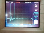
IMG_20150221_171436.jpg
Here is the waveform which I have captured at the conditioning circuit output
 
  • Like
Reactions: Dont

    Dont

    Points: 2
    Helpful Answer Positive Rating
Status
Not open for further replies.

Part and Inventory Search

Welcome to EDABoard.com

Sponsor

Back
Top