Continue to Site

Welcome to EDAboard.com

Welcome to our site! EDAboard.com is an international Electronics Discussion Forum focused on EDA software, circuits, schematics, books, theory, papers, asic, pld, 8051, DSP, Network, RF, Analog Design, PCB, Service Manuals... and a whole lot more! To participate you need to register. Registration is free. Click here to register now.

Malfunction of PIC16F877A

Status
Not open for further replies.

kappa_am

Full Member level 6
Joined
Jul 16, 2012
Messages
331
Helped
19
Reputation
38
Reaction score
19
Trophy points
1,298
Location
Vancouver
Activity points
3,859
hi all,
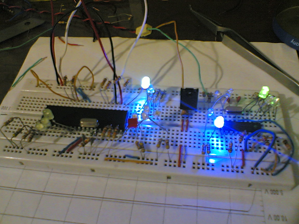
I am examining a program with PIC16F877, outputs are LEDs. It is programmed well, but it does not work well. when I touch it case (not pins just black case near pin1), on each touch it display various results on LEDs and sometimes correct answer. all input pins have pull-down resistor. master clear pin is pulled up by a 10K resistor, and all interrupts are disabled.
I am really confused! what's the problem?!!

I would be grateful if some one help me with this problem. :)
 

Is using breadboard/protoboard???

If yes, remove the pins of osc and crystal from protoboard!!!
 

Attachments

  • WP_20150103_16_33_39_Pro.jpg
    WP_20150103_16_33_39_Pro.jpg
    927.2 KB · Views: 89
Last edited:

thank you for your reply and the picture.
but No Result, yet.

- - - Updated - - -

the problem is related to master clear pin when I touch it with probe of Volt meter it works and after e few second it get off.
it looks like capacitor related problem!! I thought it is problem of the breed board and I have changed it but no result!
 

What voltage are you actually measuring on the -MCLR pin?

It sounds like the pull-up resistor is open circuit or far higher than the 10K you think it is.

Brian.
 

5.11V
I reduced it to 6.8K. but doesn't help.
 

OK, then either you have a seriously bad construction, are missing decoupling capacitors or you are actually resetting the processor with your probe but the watchdog timer is almost immediately shutting it down again.

From your photograph I can't see the crystal loading capacitors or any decoupling capacitors but they may be out of camera shot. Please post the exact schematic of your circuit so we can see.

Brian.
 

Brian (betwixt), the photo is mine!!! Is only a example!!! Caps is in other side!!!

Maybe the problem is a fuse or watchdog, or power supply (5V11 is higher)...
 
Last edited:

Oops! Sorry Nagkiller, I looked back through the messages and didn't notice it was from you instead of Kappa_am.

I'll start again....

Kappa_am, can you post a photograph and exact schematic please.

Brian.
 

Watchdog has been disabled. on the other side of the board a PIC of 16 series is working well so I do not think the problem is power supply; furthermore I have implemented many PIC base project mainly 16 and 18 series with this supply without problem. please find the picture of the circuit attached. since this is not real project and just has been implemented to check some performances I have not its schematic, but tomorrow I will try to implement it by Proteus. so I can send the schematic tomorrow. it's very simple 2 bit of port B and whole of port C are inputs, port D and portE are outputs. all ports have pull-up or pull-down resistors.

Thank you for your kindness and helps :)


In my photo, it is a PIC16F76, its not run properly into protoboard, the same symptoms, the solution is remove the pins of osc (Pin 13 and 14) from protoboard (lift), and works fine!!!

Capacitors (27pF) are smd package and is in another side.

Which is the voltage in PIN11??? 5V or 7V5 ???

Post the code too...
 
Last edited:

here is the code
Code:
  unsigned short PS[3], CH, CHO, CHN, CHZ, DCH, CL[3], IPH[3]={1,1,0}, CL1, PSO1;
void main() {
OPTION_REG=0x87;
INTCON=0x00;
TRISD=0x00;
TRISC=0xFF;
TRISE=0x00;
TRISB=0xFF;
TRISA=0x00;
PORTA=0;
CH=0;
 PORTE=0x03;
    delay_ms(5000);
while(1) {
 CHO=0;
   CH=(PORTB & 0x06)>>1;
   PORTE=CH+4;
   delay_ms(5000);
  while(CHO==0) {
   if((PORTC & 0x03)==CH) {
   CL[0]=PORTC>>2;
   PORTE.B2=0;
   CHO=1;}}
   PORTD=CL[0];
   delay_ms(5000);
//////////////////////////

          }   }
the 5s delays are added to see what is happened on output.
the voltage on pin 11 =5.11V

- - - Updated - - -

The problem is solved by adding a 22uF capacitor to the output of the 7805!
just there is another problem in code. that is:
Code:
   PORTE.B2=0;
this line turn entire PORTE zero not just 3rd bit. why?
 

Because is missing ADCON register, make all pins as digital!!!

And maybe by PORTE=CH+4;

Try this code:

Code:
//unsigned short PS[3], CH, CHO, CHN, CHZ, DCH, CL[3], IPH[3]={1,1,0}, CL1, PSO1;
const unsigned long temp = 1000;
void main()
{
  OPTION_REG=0x87;
  ADCON1 = 0x0F;
  INTCON=0x00;
  TRISA=0x00;
  TRISB=0xFF;
  TRISC=0xFF;
  TRISD=0x00;
  TRISE=0x00;
  PORTA=0;
  PORTB=0;
  PORTC=0;
  PORTD=0;
  PORTE=0x03;
//  CH=0;
  delay_ms(temp);
  while(1)
  {
    delay_ms(temp);
    PORTE.B2=1;
    delay_ms(temp);
    PORTE.B2=0;
    //////////////////////////
  }
}
 
Last edited:
Because is missing ADCON register, make all pins as digital!!!

And maybe by PORTE=CH+4;
1. nonsense, ADCON is only affecting digital input functionality
2. hits the point
 

1. It makes sense yes, ADCON1 missing cause the problem once!!!
Just comment the line with ADCON1 (in my posted code), compile and see the results!!!
But, maybe I'm wrong!!!

My version is mikroC Pro for PIC 6.5.0 (NOT REGISTERED)!!!

Now, I look the datasheet for ADCON1 (You left me with doubts):
Code:
4.5 PORTE and TRISE Register
PORTE has three pins (RE0/RD/AN5, RE1/WR/AN6
and RE2/CS/AN7) which are individually configurable
as inputs or outputs. These pins have Schmitt Trigger
input buffers.
The PORTE pins become the I/O control inputs for the
microprocessor port when bit PSPMODE (TRISE<4>) is
set. In this mode, the user must make certain that the
TRISE<2:0> bits are set and that the pins are configured
as digital inputs.[B][COLOR="#0000FF"] Also, ensure that ADCON1 is configured
for digital I/O[/COLOR][/B]. In this mode, the input buffers are
TTL.
 
Last edited:

Thanks you all for your helps.
your proposed code does not what I expected. however, I modified my code base on your advice, and it is ok to this stage. I use B2 of PORTE as external interrupt of the other PIC and two other output B0 and B1 of portE as data selection.
I will delete all delays and connect them to each other. hope another problem would not rise.

The only problem that I dealt with when I have not configured ADCON register was that I had not no access to individual bits, and turning one bit zero was turning all port zero.
 

A problem with PIC16F819:
when the circuit is turned on first time port B does not work. to get it working I have to disconnect and connect external interrupt or connect . disconnect supply several time rapidly! after the portB gets ON it works properly. The code is as below.
Code:
unsigned short rep, OUTM[3]={136, 85, 14};
interrupt(void) {
if (INTCON.INTF){
INTCON.INTF=0;
rep=(PORTB & 0x06)>>1;
 PORTA=OUTM[rep] & 0x0F;
 PORTB=OUTM[rep] & 0xF0;
   }}
void main() {
 OPTION_REG=0xc7;
  ADCON0=0x00;
  ADCON1=0x07;
 TRISA =0xF0;
 TRISB =0x0F;
 INTCON=0x90;
  PORTA=0x00;
  PORTB=0x00;
  while(1);
  }

I have seen several weird things in this circuit.


P.S: portA works properly
 

I believe you have a hardware problem, nothing that can be found in the code. E.g. unreliable processor reset, non-monotonous power supply rise, possibly latch-up. Or problems in the external circuit unrelated to the processor.
 

Status
Not open for further replies.

Similar threads

Part and Inventory Search

Welcome to EDABoard.com

Sponsor

Back
Top