Continue to Site

Welcome to EDAboard.com

Welcome to our site! EDAboard.com is an international Electronics Discussion Forum focused on EDA software, circuits, schematics, books, theory, papers, asic, pld, 8051, DSP, Network, RF, Analog Design, PCB, Service Manuals... and a whole lot more! To participate you need to register. Registration is free. Click here to register now.

Transformer centre tapped or normal

Status
Not open for further replies.

jit_singh_tara

Full Member level 6
Joined
Dec 22, 2006
Messages
325
Helped
9
Reputation
18
Reaction score
4
Trophy points
1,298
Location
Delhi , India
Activity points
4,293
Dear Friends ,

I am using 7-0-7 transformer rated 150mA .

I am generating 2 supplies :
1.5V regulated power supply .
2.8V unregulated power supply.

Drawing 140 mA from the ckt.

I am drawing 140 mA from the ckt . My transformer is heating . I am afraid that by using 7-0-7 transformer i am using only half of the secondary winding that way i am trying to pull 140mA from the 75mA winding . Please suggest if i am right .

PLease let me know the difference between efficiency of normal transformer and centre tapped transformer .
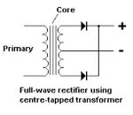
 

I am using transformer in this configuration :

centre tapped transformer.png


Please let me know whats the difference in using transformer 7-0-7 rated 150mA and 0-7 rated 150mA . I will be generating 5V dc using 7805 . Will the current supplying capability be same in both the transformers .
 

Do you have transformer datasheets? Do they have same VA rating?
I will be generating 5V dc using 7805 .
I though you were
generating 2 supplies :
1.5V regulated power supply .
2.8V unregulated power supply.
 
I am generating 5V for running mcu and display and 8v for relay . Overall i am drawing 140mA . My transformer is rated 150mA. It is heating too much .

I want to know that if a centre tapped transformer is rated 150mA , and i am using it in the config as shown in the fig . Then am i drawing 140mA from the complete secondary winding or i am using only the half of the winding.....?
Because my transformer is heating too much....
 

A half wave rectifier is less efficient in terms of transformer utilization than a full wave type. With 140 mA DC you'll around the rated rms current of the 2x7/150 mA transformer. So it will surely heat up.
 
But i am using the centre tapped transformer followed by the full wave rectifier ...

If i use 0-7 transformer of the same rating followed by a bridge will it solve my purpose . i.e will it reduce the heating of the transformer......
I think by doing this i will be utilizing the full secondary winding for drawing the current though the drop will be more bcoz of 2 diodes in either direction.....
 

Either

get a proper sized VA & V transformer so it doesn't over heat or ...

provide full BOM , Schematic and pictures to analyze your problem..

You could be saturating the core with too big a capacitor. running at 10% ripple 20x the peak power or you could have the transformer enclosed in plastic which may run too hot.
 

But i am using the centre tapped transformer followed by the full wave rectifier ...

If i use 0-7 transformer of the same rating followed by a bridge will it solve my purpose . i.e will it reduce the heating of the transformer......
I think by doing this i will be utilizing the full secondary winding for drawing the current though the drop will be more bcoz of 2 diodes in either direction.....

You are fully utilizing the power rating of the transformer try some more current rating like 300mA, 0 - 7V transformer. It will never heat.
 

But i am using the centre tapped transformer followed by the full wave rectifier ...
Sorry, my fault. I said half-wave but meaned full-wave dual-diode.
 

What does it means it is heating too much? Allowed temperature rise for small transformer can be 55°C.
 

What does it means it is heating too much? Allowed temperature rise for small transformer can be 55°C.

I am not able to touch the transformer after some time..for too long
...I have to enclose it in 48x48x 80 mm plastic enclosure
it makes the unit very hot including the pcbs......
 

Let me repeat. You either choose better transformer or show your design. One example is using asymmetric loads on taps that causes saturation and melt-down. e.g. A half and full bridge on same transformer.

I am generating 5V for running mcu and display and 8v for relay . Overall i am drawing 140mA . My transformer is rated 150mA. It is heating too much .

I want to know that if a centre tapped transformer is rated 150mA , and i am using it in the config as shown in the fig . Then am i drawing 140mA from the complete secondary winding or i am using only the half of the winding.....?
Because my transformer is heating too much....
 

A cheap (Chinese from ebay?) transformer uses thin wire with a high resistance and not enough iron in its core.

I have a cheap 9V/100mA AC/DC adapter (guess where it was made) that has an output higher than 18V with no load and with no load it gets HOT!
With a 100mA load its output is 9V and it does not get much hotter.

I have a 9V/300mA AC/DC adapter and its output with no load is about 12V. It is warm with no load.

I have some 9V/500mA AC/DC adapters that have been plugged in for months and are driving battery chargers with blinking LEDs. They are rarely used for charging and are at room temperature.
 

You can't draw the full rated current from a transformer with a rectifier-capacitor load. Due to the high peak current drawn from the transformer by a rectifier-capacitor supply, the RMS current in the transformer is much higher than the DC output of the rectifier-capacitor. Typically the RMS current value is about 1.6 of the DC output so the DC output should be no more than about 60% of the transformer rating for this reason.

Thus for a transformer rating of 150mA, you should draw no more than about 90mA DC from the full-wave rectifier-filter. That's why your transformer is heating up with a 140mA DC load.
 
What are these values?
  1. primary winding resistance
  2. secondary winding resistance to centre tap
  3. VA rating
  4. V rating
  5. Frequency rating
  6. Load Capacitance
  7. Load resistance or current peak, avg , RMS
 

Check the transformer without load to see if it still get hot.
 

I have a cheap 9V/100mA AC/DC adapter (guess where it was made) that has an output higher than 18V with no load and with no load it gets HOT!
With a 100mA load its output is 9V and it does not get much hotter.
Then what is the theory behind that, Transformer heating on no load and reducing heat in when loading sounds like a CT Isnt it?

You can't draw the full rated current from a transformer with a rectifier-capacitor load. Due to the high peak current drawn from the transformer by a rectifier-capacitor supply, the RMS current in the transformer is much higher than the DC output of the rectifier-capacitor.
I am totally agree with this.
 
The only solution is to select transformer with higher VA rating as suggested before.

FvM is right in answering to my previous post so I changed my answer.
Thanks.
 
Last edited:

In other words rectifier with smoothing capacitor represent capacitive load to transformer. Transformer power rating expressed in VA can be exceeded even when real power is only half of that. Then transformer get hot because of large out of phase currents.
In fact, it's more the distortion than the reactive power factor that enforces a higher transformer VA. Center tapped transformer circuits are at an additional factor 0.7 disadvantage due to non-continuous (alternating) current flow.

All in all, you need typically +40% VA for bridge rectifier DC supply and +100% for center-tapped full-wave rectifier. In detail, capacitor size and transformer leakage inductance and winding resistance matters.

Heating at no load is a different thing, caused by core losses when the transformer is designed with unsuitable high flux.
 
Status
Not open for further replies.

Similar threads

Part and Inventory Search

Welcome to EDABoard.com

Sponsor

Back
Top