b2rster
Junior Member level 1
- Joined
- Nov 2, 2006
- Messages
- 15
- Helped
- 0
- Reputation
- 0
- Reaction score
- 0
- Trophy points
- 1,281
- Location
- Monywa, Myanmar
- Activity points
- 1,365
Follow along with the video below to see how to install our site as a web app on your home screen.
Note: This feature may not be available in some browsers.
Hi,
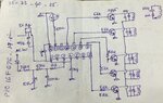
The R on pin3 of PIC is not necessary. ( I even think it makes things worse)
The coils have no supply.
I have no idea how this should work.
At least a little description would be helpful.
Klaus
Your PIC is not empty, it is protected from copying :smile:
1. Pay a company a lot ($10,000s) to reverse engineer the chip, either by (a) decapping it and analysing with a microprobe, or (b) by functional analysis.
2. Do (a) or (b) yourself... my money would go on (b) as probably successful.
3. Contact the manufacturer and ask them.


I asked you to mention what voltages you get when input to transformer is increased from 180V to 270V in step of 5V. I need to know this. This will tell what relay has to be operated at what voltage.

Ok. I will post a code in a day or two.
I have done the coding and it is 99% complete. One more thing I want to know is which relay is 1 and which are 2, 3, 4, 5 ?