Continue to Site

Welcome to EDAboard.com

Welcome to our site! EDAboard.com is an international Electronics Discussion Forum focused on EDA software, circuits, schematics, books, theory, papers, asic, pld, 8051, DSP, Network, RF, Analog Design, PCB, Service Manuals... and a whole lot more! To participate you need to register. Registration is free. Click here to register now.

[SOLVED] PIC Design, State of Madness, Mayhem, Trauma

Status
Not open for further replies.

KhaledOsmani

Full Member level 6
Joined
May 4, 2014
Messages
384
Helped
1
Reputation
2
Reaction score
1
Trophy points
18
Activity points
3,933
Hello,

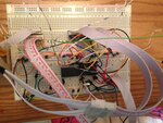
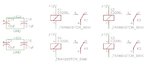
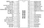
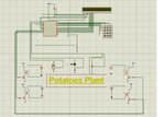
I`m connecting a PIC, to four open-circuit relays, whereas the loads, are of 220V, basically ranging between 10W, 19W, and 20W, only one of them (I`m not making it turn off frequently) is of 1KW.

When connected, two of the four, sometimes one,
the pic GOES COMPLETELY CRAZY, either it:

Reset randomly
Takes decision from its own
slows down, to half its original speed...

Why could this happens to a PIC, why a PIC would "lose its mind", and go as slowly as it could be.
Is it because of the open-relay switch connections? notice that 3/4 of the loads, are very low power, one is a valve, other is a fan, final is a LED lamp.

Any possible solutions please!
 

Hi,

There are many possible causes and many possible cures.

However you need to post a detailed schematic, your program code and preferably a picture of your actual pic and relay wiring layout for anyone to make an informed suggestion as to the actual cause/s .
 

Hi,

There are many possible causes and many possible cures.

However you need to post a detailed schematic, your program code and preferably a picture of your actual pic and relay wiring layout for anyone to make an informed suggestion as to the actual cause/s .
first never connect pic directly to a relay use at least 74hc244n
2nd:use a buffer latch controlled by pic to make sure nothing is going crazy
3rd : can also use diodes to prevent reverse current
hope it helps
Zeyad
 
here is the open relay switch that I`m using, also below is a datasheet of the pic:

As for the code, it's only logiced as, when ADC value of sensor1 = certain value, either HIGH pinx, of portx, either LOW it

- - - Updated - - -

The ADC process, is very logical and accurate and correct, but it just goes crazy, not all the time, and not for much, is just drive crazy for a certain value of another.
it's like the pic is having black days after a severe break-up
but it must have a drug
 

Attachments

  • Open Relay Switch.gif
    Open Relay Switch.gif
    14.3 KB · Views: 143
  • PIC18F4520.jpg
    PIC18F4520.jpg
    128.8 KB · Views: 150
  • Diagram.jpg
    Diagram.jpg
    101.7 KB · Views: 150

In the 'diagram.jpg' the diodes are missing from across the relay coils. They MUST be fitted or you risk damaging the driver transistor and the PIC. It might be worth considering a driver IC like the ULN2003 instead of transistors and those have built-in diodes and resistors so your component count is less.

Assuming you have them fitted, the most likely cause of the problem you see is noise on the supply line or the reset line. Take care with the wiring so none of the relay current can flow back to the PIC VSS pins and be sure to add capacitors across VSS and VDD (both pairs) as close to the PIC as you can. I suggest a 100nF ceramic capacitor and an electrolytic capacitor of 1uF - 10uF in parallel is used.

Unless the load wiring is located very close to the PIC, I don't think it has any relevance to the problem. All the issues are on the coil side of the relay, not it's contacts.

Brian.
 

Hello,

More than likely the pic was resetting because of a large voltage dip on the main power line for a noticeable amount of time. This will trigger a BOR and the PIC will reset. Relays can pull a large amount of power when activated. As mentioned above there is a large amount of power discharged right after being deactivated. (This is because relays use inductors, which discharge a large current back into the circuit in the opposite direction it was originally flowing. This can be blocked with a fly back or suppression diode.)

Since the ADC is using the main supply power lines as a reference it is also affected by the instability created by switching the relays on and off. My advice would be to add a couple capacitors to the circuit. (2x10uF and 5x0.1uF should give a noticeable improvement.) Whenever you switch something on you create a power draw, but for a short amount of time there is not enough power on the line so the voltage suffers to compensate. Capacitors are like batteries, they store a small amount of energy at a certain voltage. If the line drops below that voltage it discharges to try and bring the voltage back up. Then the power supply catches up and recharges the capacitor.

I hope this helped.
 
Assuming you have them fitted, the most likely cause of the problem you see is noise on the supply line or the reset line. Take care with the wiring so none of the relay current can flow back to the PIC VSS pins and be sure to add capacitors across VSS and VDD (both pairs) as close to the PIC as you can. I suggest a 100nF ceramic capacitor and an electrolytic capacitor of 1uF - 10uF in parallel is used.

Unless the load wiring is located very close to the PIC, I don't think it has any relevance to the problem. All the issues are on the coil side of the relay, not it's contacts.

Brian.

Yes man, the problem is a noise issue. I must filter it.
Could you please post a diagram or a schematic, telling how to add the capacitors for VSS and VDD please.

Is it from the pin of VSS/VDD and from other node to the ground/+ ?

Did you mean that I must for one pin add a ceramic capacitor, and for another pin add an electrolytic capacitor of 1uf - 10uf in parallel?

Note that, in my hardware, the distance is quite far, between sub-circuits.
i.e: the LCD is connected with a long serial cable of 8 wires, for a distance of >20Cm
the keypad is also away for 15 cm
the open circuit relay switched is far by almost 25cm from the pic.

There is a point to clarify:
I have three different sensors to add in the circuit.
What I previously did, is connected them all via the supply for the micro-controller.
no wonder it sometimes shuts down, or decrease output brightness etc....

What I will do now, is,
branch the sensors in a +5V private supply for them, different from the one branched to the pic
I will only branch the pic and the lcd and the keypad to the another +5V source.

I will branch the capacitors, to Vss and Vdd, but I will be waiting for a diagram showing how to connect them..


thanks,

- - - Updated - - -

Hello,

My advice would be to add a couple capacitors to the circuit. (2x10uF and 5x0.1uF should give a noticeable improvement.) Whenever you switch something on you create a power draw, but for a short amount of time there is not enough power on the line so the voltage suffers to compensate. Capacitors are like batteries, they store a small amount of energy at a certain voltage. If the line drops below that voltage it discharges to try and bring the voltage back up. Then the power supply catches up and recharges the capacitor.

I hope this helped.

how to add these capacitors?
 

The capacitors go between VDD and VSS. I would use ceramic capacitors for the 0.1uF capacitors these are not polarized so either lead can be connected to ground. For the 10uF capacitors, I would use electrolytic capacitors. These are polarized. So one pin must be connected to ground (VSS) and the other lead to the positive side (VDD). The lead that connects to ground is usually marked with a bar or a strip. I always recommend using capacitors that are rated at two or three times the voltage of VDD.

The capacitors can go anywhere really but they are more effective the closer they near the device that is doing the switching. So I may put 3 0.1uF capacitors near the microcontroller the rest near the relays or the power supply. Then put 1 more near the LCD and each of the sensors.

The distance of the wires may cause interference and speed issues, but for power its not really an issue at all.

You can use the same supply, just make sure that it can supply enough current for everything. If you pull too much some supplies try to cut off to prevent damage to the supply. Just a friendly reminder, if you use private supplies you need to connect the grounds together so that everyone can talk to each other.
 
You should have the two VSS pins linked together and the two VDD pins linked together. On both sides of the PIC, as close as possible to it, wire a 100nF ceramic capacitor AND at least a 1uF capacitor in parallel. The reason why you are getting the resets is because the supply lines and ground all have other currents flowing through them, particularly the relay current which is probably many times more than the PIC uses. When current flows through a wire two things happen, one is that you lose some voltage because of the resistance of the wire and the other is inductance in the wire stops sudden changes in current. Together they make it likely that when things are switched on and off by the circuit, the supply across the PIC varies and causes it to reset or crash. The capacitors at each of the VSS/VDD pins work as local voltage reservoirs, they even out the changes in voltage and make the PIC less susceptable to the variations along the supply lines.

As a general point, try to keep the current flowing through the relays away from the PIC supply as much as you can. Try to wire the ground side (transistor emitters) back to the power suppy and the positive relay side back to the power supply independantly of the PIC. In other words, with the PIC VDD and VSS not sharing the same power and ground wiring. That will keep the voltage drops away from the PIC as much as possible.

Brian.
 

Try replacing the transistor drivers with opto-isolators. Run the relays off a separate power supply with both +5 and ground isolated from the PIC power supply. With the opto-isolators, you do not need the common ground between the relays and PIC.
 

the relays operate at 12V
their source is different than the main supply voltage (5V)

I just connect the ground of +5V and +12V together


please is there any diagram or photos to see experimentally?

and as a conclusion, the only solution is to put capacitors? this craziness disappear? i've understood what does this craziness mean.
 

this is the real hardware:
 

Attachments

  • photo(18).JPG
    photo(18).JPG
    2.5 MB · Views: 152

Hmmm..... I've seen better layouts - but it looks very pretty :smile:

To be honest, I am not in the least suprised you are having a reset problem. The power wiring is not good!
Think of it this way, if you supply power at one end of a wire and draw current from the other end, a voltage will be dropped along it's length. That means the voltage at points along it's length will all be different, anything connected along the length will have a portion of the voltage drop on it. When you connect lots of circuits by running power wires from one board to another, each board will have a different ground voltage and supply voltage with respect to the others and how much that is depends on how much current flows along the wires.

Yes, connect the +12V ground and +5V ground but use a different wire for each and only join them at the power supply (silver 9V battery ?) so the current for one doesn't flow along the same wire as the other. I can't see a 5V regulator but wherever it is, make sure there is a capacitor 1uF or similar across it's input pin and ground pin and another capacitor between it's output pin and ground pin, keeping them as close to the regulator as possible. Also make sure the ground of the regulator is connected to the PIC ground and not the 12V ground wire.

It can be done - and it can be reliable. I have a PIC16F628A here which is controlling five relays every few minutes and they are all rated at 30A and switching 2HP (about 1,500W) motor loads. It has been working for several years and never crashed once!

Brian.
 

Here is a close look to the PIC:

Isn't adding capacitor, one pin connected to Vss the other to Vdd, is an act of short-circuit?
Note that Vss and Vdd are connected on both sides of the pic, means that one is at +5V other is at 0V so the entire circuit (of PIC + KEYPAD + LCD) is fed up from these two terminals.
I connect the capacitor across the whole supply source?
please, clear explanations, (short ones too lol, thanks)

- - - Updated - - -

@betwixt

Conclusion:

Add a 1uf electrolytic capacitor across the voltage regulator1. (+5V for the PIC, keypad, LCD)
add a 1uf electrolytic capacitor across the voltage regulator2. (+5V for the LDR/LM35DZ/SOIL MOISTURE sensors).
Connect all grounds together (ground of first 5V, and ground of second 5V, and ground of 12V, with different wires, all grouped on the ground of the two +5V supplies)

What about ceramic/electrolytic capacitors accross Vss and Vdd? How to connect them?

From another part, the ADC process was working great earlier when there was no private power supply for the sensors (when the sensors take voltage from the pic supply). Now, when they have a private supply, the conversion isn't efficient, nor correct, also not forgetting to mention, I placed the sensors +20cm far from the pic, (earlier they were closer) I know that when length increases, resistivity increases, could that be a reason for a voltage drop, and results to wrong adc? Solution? [are my questions clear? Am I giving full explanations to the state]?

- - - Updated - - -

, as close as possible to it, wire a 100nF ceramic capacitor AND at least a 1uF capacitor in parallel. The capacitors at each of the VSS/VDD pins work as local voltage reservoirs, they even out the changes in voltage and make the PIC less susceptable to the variations along the supply lines.


Brian.

I really couldn't understand the truth behind your words.
words cannot draw your thoughts.
Can you please tell me more about capacitor connections idea, how to make it, the keywords like AND, BRANCH, ACROSS, are making me confuse....

- - - Updated - - -

As a summary, what all steps that I should do, so the circuit is complete (except for being a nagger :p)

- - - Updated - - -

What I had also noticed, is that not all times the PIC resets. Sometimes it work as supposed, randomly otherwise, it just resets.

the Sensors are working fine, when disconnected from the circuit, but once connected, wrong values are shown on the LCD, noting that, yesterday they were showing 100% efficient values, I had not changed anything in code, but I changed in the hardware, (distances) so the results are damaged. Note also, when a value changes, let's say I put the soil moisture sensor, in water, and moisture increases from 3,4% to 80% the temperature automatically, dramatically changes, and give output as 60C when it was 7C.

The reset occurs most times when switching on/off occurs at the relays, no reset occured before getting into the relay stage.

final note: the PIC voltage source is of 5.01V ; the sensor's voltage source is of: 4,98 V

- - - Updated - - -

The capacitors go between VDD and VSS. I would use ceramic capacitors for the 0.1uF capacitors these are not polarized so either lead can be connected to ground. For the 10uF capacitors, I would use electrolytic capacitors. These are polarized. So one pin must be connected to ground (VSS) and the other lead to the positive side (VDD). The lead that connects to ground is usually marked with a bar or a strip. I always recommend using capacitors that are rated at two or three times the voltage of VDD.

The capacitors can go anywhere really but they are more effective the closer they near the device that is doing the switching. So I may put 3 0.1uF capacitors near the microcontroller the rest near the relays or the power supply. Then put 1 more near the LCD and each of the sensors.

The distance of the wires may cause interference and speed issues, but for power its not really an issue at all.

You can use the same supply, just make sure that it can supply enough current for everything. If you pull too much some supplies try to cut off to prevent damage to the supply. Just a friendly reminder, if you use private supplies you need to connect the grounds together so that everyone can talk to each other.

Vss is the ground and Vdd is +5V. If I put the capacitor in between, isn't this a form of short-circuit?
What do you mean put capacitor for power supply/lcd/ etcc.....

Could you explain in steps? do you have any diagrams?
 

Attachments

  • photo 1.JPG
    photo 1.JPG
    2.7 MB · Views: 134
  • photo 2(1).JPG
    photo 2(1).JPG
    2.6 MB · Views: 139
  • photo 3(1).JPG
    photo 3(1).JPG
    2.7 MB · Views: 131

Isn't adding capacitor, one pin connected to Vss the other to Vdd, is an act of short-circuit?

This is true for fully charged inductors. For capacitors, they are an open circuit when fully charged. So capacitors are only present in the circuit when they are charging or discharging. This is why they are used for decoupling and reacting to loads on the line.

What do you mean put capacitor for power supply/lcd/ etcc.....

For this circuit you will want to add many capacitors. For each regulator you should add input and output capacitors as described in its datasheet. This is required for regulator output stability.

For the PIC you should place 5 0.1uF capacitors as close as possible to it, between its VDD and VSS connections. This is usually recommended in the datasheet under hardware recommendations or considerations.

For the LCD you should place 1 0.1uF capacitor as close as possible to it, between its VDD and VSS connections. This may be already done on the lcd but one more will not hurt anything.

For each sensor you should place 1 0.1uF capacitor as close as possible to it, between its VDD and VSS connections. Again this may be already done if using a breakout board, if not it is good practice to add one for each sensor.

For the relays you place 2 10uF capacitors and 2 0.1uF capacitors as close as possible to it, between its VDD and VSS connections. This is to suppress the massive load swings caused by activating the relays.
 
Last edited:
is this what you ment? (sure with no voltage regulator, and with +5v not +12V)

- - - Updated - - -

The capacitors can go anywhere really but they are more effective the closer they near the device that is doing the switching. So I may put 3 0.1uF capacitors near the microcontroller the rest near the relays or the power supply. Then put 1 more near the LCD and each of the sensors.

How to connect capacitors on the sensors

- - - Updated - - -

For the relays you place 2 10uF capacitors and 2 0.1uF capacitors as close as possible to it, between its VDD and VSS connections. This is to suppress the massive load swings caused by activating the relays.

this and you mean as 2 o.1 uF paralleled with 2 10 uF ?
 

Attachments

  • qLcev.png
    qLcev.png
    6.7 KB · Views: 128

Below I have attached a few examples.

You should not connect the +5V outputs from two regulators together. The reason for this is that the current draw is not equal. Refer to regulator datasheet for input output capacitor values.
 

Attachments

  • Example.jpg
    Example.jpg
    174.3 KB · Views: 121
  • LCD and Sensor Example.jpg
    LCD and Sensor Example.jpg
    78.7 KB · Views: 131
  • PIC Example.jpg
    PIC Example.jpg
    172.4 KB · Views: 128
  • Regulator Example.jpg
    Regulator Example.jpg
    76.2 KB · Views: 127
  • Relay Example.jpg
    Relay Example.jpg
    120.2 KB · Views: 129
Last edited:
What is the point of connecting 100nf ceramic parallel with bunch of 1uf electrolyc between vss and vdd why not getting enough from 100nf. Or else why not to put only one capacitor equivalent of these many paralleled capacitors?

why to have ceramic and electrolytic?

same output concerning sensors after addition of 0.1uf between each sensor VSS and VDD (note I still not connected capacitors with the regulator circuit)
 

What is the point of connecting 100nf ceramic parallel with bunch of 1uf electrolyc between vss and vdd why not getting enough from 100nf. Or else why not to put only one capacitor equivalent of these many paralleled capacitors?

The reason for this is reaction time. The 100nF ceramic is good at reacting to small ripples very quickly but the large 1uF is not. Likewise the 1uF is good at reacting to large ripples were as the 100nF is too small to help.

why to have ceramic and electrolytic?

Ceramic vs electrolytic is a huge topic. For small capacitor value it is better to get ceramic. For large capacitor value it is best to get electrolytic.

same output concerning sensors after addition of 0.1uf between each sensor VSS and VDD (note I still not connected capacitors with the regulator circuit)

You need to connect the capacitors for the regulators before you try anything else. Most regulators require at least some kind of output capacitor (usually a tantalum capacitor) for output stability.
 
Hello!

It's time to switch to modern designs. A relay is a mechanical device,
therefore unreliable. (Un-relay-able??).
Why not using solid state relays?

In the past, I have used a Sharp S216S02. It can drive more than 1000W
(and I guess there is no problem for smaller loads, but in this case you may want to use
cheaper devices).
Among the advantages, there is a 0 detection mechanism for switching, and therefore
you don't broadcast much switching noise in the neighbourhood.
As it's opto isolated, you can drive it directly from your micro controller like a LED.

I'm using it to drive an oven-toaster to solder BGA chips.

Dora.
 

Status
Not open for further replies.

Similar threads

Part and Inventory Search

Welcome to EDABoard.com

Sponsor

Back
Top