Continue to Site

Welcome to EDAboard.com

Welcome to our site! EDAboard.com is an international Electronics Discussion Forum focused on EDA software, circuits, schematics, books, theory, papers, asic, pld, 8051, DSP, Network, RF, Analog Design, PCB, Service Manuals... and a whole lot more! To participate you need to register. Registration is free. Click here to register now.

HFSS to model microstrip patch antenna FOR Receiving radiation.

Status
Not open for further replies.

eztucker

Junior Member level 2
Joined
Apr 29, 2013
Messages
20
Helped
4
Reputation
8
Reaction score
4
Trophy points
1,283
Activity points
1,464
Hello,

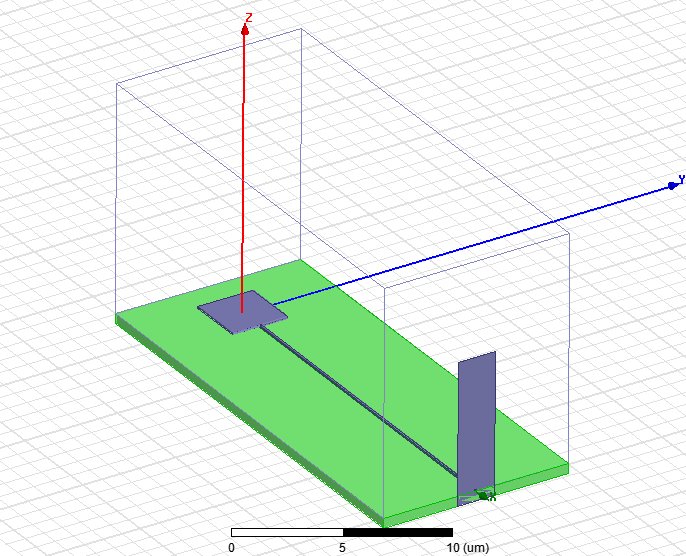
I have a simple question. I am modeling a microstrip patch antenna as a receiving antenna where the microstrip is terminated by a wave port to "receive" any propogating waves from the patch, which is excited by a plane wave. My question is simply: Do I need to define an integration line when using a wave port to receive radiation or will that actually excite a mode at the wave port? I have attached a picture of the model. Thanks!


Also, if anyone has an example for simulating a receiving antenna, that would be very helpful!
 

if you are exciting your model by plane wave, why do you need wave port? You can use incident wave as you excitation source.
Integration line usually helps you align the entering E-field. And also to calculate E dot dl along the line to calculate voltage, which is later on used to calculate Power/voltage characteristic impedance.
 

Hey Newbie_ece,

Thanks for your response.


if you are exciting your model by plane wave, why do you need wave port? You can use incident wave as you excitation source.

I just need something to terminate the micostrip line to absorb the waves that travel down the transmission line (because I don't want any surface waves to reflect off the boundary where it ends). I have an incident plane wave as my source and ONLY want that as my source (as you hinted at). Should I use something else to terminate the transmission line, a pml maybe?

Integration line usually helps you align the entering E-field. And also to calculate E dot dl along the line to calculate voltage, which is later on used to calculate Power/voltage characteristic impedance.

So does an integration line actually excite a mode? If so, then I assume that without one, you are not using it to excite the structure...?
 

I see what you are trying to do.
You can use waveport to absorb the waves down the line. Since you dont want to excite the waveport, if you right click on fields, you can set the magnitude of Power of waveport to 0 and incident wave to 1. This will make waveport act as an absorber and no extra energy will enter.
You can draw a rectangular sheet on the waveport and use field calculator to integrate the poynting vector on that sheet, which will give you the power wave port has absorbed.
When you assign an waverport and if its magnitude is greater than 0, waveport will always excite a mode. Integration line has nothing to do it. Like I said integration line just lets you align the modes. Even if you dont have Integration lines, waveport will be active.
 
You can use either a waveport or a lumped 50 ohm (if your line is 50 ohm) at the end of you line.
If you use a waveport you have to be careful about the size of the waveport to cover enough area around the ustrip line and also you have to check the excited modes. What I see here is that the height of your line is much bigger than its width (although both seem to be enough) I wonder if your first mode is the ustrip mode or not. It may excite WG mode sometimes which is very confusing.
 
If you use a waveport you have to be careful about the size of the waveport to cover enough area around the ustrip line and also you have to check the excited modes. What I see here is that the height of your line is much bigger than its width (although both seem to be enough) I wonder if your first mode is the ustrip mode or not. It may excite WG mode sometimes which is very confusing.

Hey Hadi-Alik,

Thanks for your response! You guys seem to know a lot more than me about this stuff, I just pretend to be an electrical engineer!

I think I will stick with the wave port since I don't know the impedance of my line at all. So to check the excited modes you mean to look at the field pattern on the wave port (Vector E-field) after I solve the simulation (since I am using it to absorb the wave, not excite any sort of modes)? I think that makes sense, I will try that. Much appreciated :)

¨Dear Extucker.

Have you achieved to simulate that?
Regards
 

Hey Daniel,

I got stuck on another project and didn't work on this for a while, but have just returned to this issue. At the moment I have mostly solved my issue, except I think it still doesn't work great because one of the radiation boundaries is too close to the patch antenna.

Basically, I have been running a parametric sweep for the waveport width and height for each simulation, then select the one that seems to yield the least amount of reflection from the waveport (as evidenced by a decaying field along the microstrip line without nodes or anything suggesting reflection). Also, I check the field pattern at the waveport to make sure it isn't showing a waveguide mode, which can happen if you make the wave port too big.

Are you working on a similar problem? Please share your thoughts or your issue, maybe we can help each other out!

-Eric


¨Dear Extucker.

Have you achieved to simulate that?
Regards
 

Status
Not open for further replies.

Part and Inventory Search

Welcome to EDABoard.com

Sponsor

Back
Top