mtwieg
Advanced Member level 6
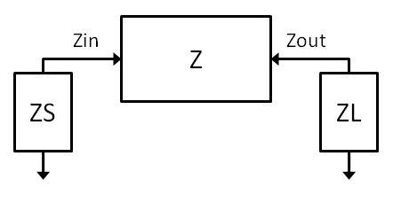
I'm trying to optimize an impedance transformer for the output of a narrowband RFPA. Let's presume I have an antenna impedance ZA and the output impedance of my amplifier is Zamp. I want my impedance transformer to present the optimum load impedance Zol to the amplifier. Zol, is not a conjugate match of Zamp; it's something different in order to maximize efficiency as opposed to power transfer.
Obviously there are tons of possible ways to implement this impedance transformation, but what if we also care about the impedance seen by the antenna port looking back towards Zamp through the transformation network (we'll call this Zs)? Are there any theoretical constraints on what that impedance Zs can be given ZA, Zamp, and Zol? Assuming a lossless, reciprocal transformation network, but with no constraints on the construction of the network.
Thanks in advance.