Continue to Site

Welcome to EDAboard.com

Welcome to our site! EDAboard.com is an international Electronics Discussion Forum focused on EDA software, circuits, schematics, books, theory, papers, asic, pld, 8051, DSP, Network, RF, Analog Design, PCB, Service Manuals... and a whole lot more! To participate you need to register. Registration is free. Click here to register now.

Can anyone spot a problem in this Current mirror circuit?

Status
Not open for further replies.

Teejayzz

Newbie level 4
Joined
Sep 20, 2013
Messages
6
Helped
0
Reputation
0
Reaction score
0
Trophy points
1
Activity points
48
Hi,
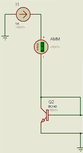
I have made this current mirror circuit in proteus isis 7.10.

https://www.dropbox.com/s/qtlb0saaqmd9wr5/Cmirror.png

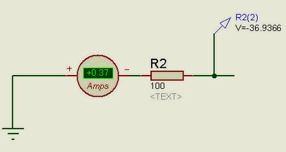
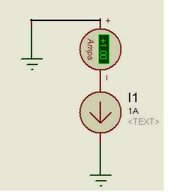
As Q1 and Q2 form a current mirror, the current AMM1 = 1A therefore AMM2 should also be 1A! but AMM2 here is 0A, so does AMM3. Can anyone tell what is wrong in this circuit? could it be an error by proteus itself? Please analyse and verify this circuit.


(NOTE: the current mirror is basically used to bias npn transistor Q3)
 

There cannot be any current in Q3 - the base is at 0V and the emitter of Q1 is at 0V so Q1 just saturates. Look at the voltage on Q1 collector.

Keith.
 

the base is at 0V and the emitter of Q1 is at 0V

This is the problem actually.. there should be a current in the base of Q3 and the voltage at base should be positive! If we just remove the current mirror and place a constant current source there at the emitter of Q3, then it works fine. It should also work fine with current mirror!
 

No. If you put the base of Q3 at 0V then that that is where is will stay! Why have you got Q3 there anyway? Without it the circuit will produce a current in R2. If you are trying to eliminate base current errors or create a Wilson current mirror to raise the current source resistance then you have drawn it incorrectly.

Keith
 

No i m not making a wilson current mirror. I am just trying to bias Q3 transistor using a normal current mirror. I am trying to use current mirror as a constant current source at the emitter junction of Q3, to bias the transistor Q3.
biasing.png
As you can see in this image, I have just replaced current mirror with constant current source I1 (and done nothing else) and the whole circuit is working fine. Base of Q3 was or is never grounded as there is a resistor R2=100 ohm in between, so its wrong if you say that base is at zero volts. As you can see, the base of Q3 is at -36.93V and not zero.
 

By replacing the current mirror with a current source you have pulled the emitter of Q3 below 0V - check the voltage and see. The original circuit you have posted cannot do that because Q1 emitter is at 0V. You haven't explained what you are trying to do and what the addition of Q3 to the current mirror is trying to achieve. "biasing Q3 with the current mirror" doesn't mean anything.

Keith

- - - Updated - - -

Just to add, a current source in a simulation will generate whatever voltage is necessary to create the current - even an impossibly stupid voltage. So, you need to use them with care.
 

Constant current source I1 is not to be inserted as you do (in the output?). Its function is different. Most of the current should pass through R1 but it can only pass less than 100mA (10V/100R) -swithing loss. Constant current source generate its own intrnal voltage to supply specific current and you read it in on the adjusant ampere meter. That's all you got. All circuit is BS. Check V and A on each node, apply ohm's law an evaluate what is happning. Your current source willl be supplying -36.9 - 0.6Vbe = - 37.5V
6749444900_1379761994.jpg

A good example of demonstation of Ohm's law. A = V/R 37/100= 370mA. This circuit is independentent and nothing to do with rest of the circuit.
Try this. You don't need extra comonents, if you need to see 1A readings on the meter.
6810191100_1379762318.jpg

It seems you don't know, why voltage is applied and where current flows.
2513161600_1379762820.jpg


This portion also has nothing to do with resy of the circuit.
 

Just to add, a current source in a simulation will generate whatever voltage is necessary to create the current - even an impossibly stupid voltage. So, you need to use them with care.

Simulation also allows other stupid things, e.g. dissipating 100W in a small BC140 transistor, because it doesn't perform thermal modelling.

Sometimes a simulator with a kind of "TILT" indicator would be helpful.
 

@ keith1200rs
According to the book "Microelectronic circuit" by Adel S. Sedra and Kenneth C. Smith, a constant current source can be constructed using a current mirror. Basically a current mirror is a current source. All I am trying to say is if a transistor can be biased using a constant current source, then it could also be biased using a current mirror (After all, a current mirror is a current source). If a transistor works with a current source then it should work with a current mirror aswell, but in proteus its is not apparantly working as it should. It could be a problem with the proteus, because the circuit is directly taken from the book i mentioned.

Thanks,

Teejayzz
 

The thing you are missing is that a bipolar current mirror ceases to be a current source if you let the transistor saturate i.e. allow the base-collector junction to be forward biased. That is exactly what you are doing. The problem is not with Proteus - it is telling you the circuit won't work. The circuit won't work. If you put the base of Q3 at a small positive voltage (say 1V or more) it will work, although I still don't know what you are trying to achieve by feeding a constant current into the emitter of Q3. That sort of connection could be used for a cascode amplifier but I guess you are not designing one of those.

Keith
 
I plan to design cascode later on. Designing my own op-amp.
 

1A seems a lot of current for biasing an opamp!

If you look at cascode circuits you will find that the base of the cascode transistor is always fixed at a higher voltage to the emitter of the transistor below it in order to ensure the transistor doesn't saturate.

Keith
 

I believe you are also missing the fact that a simulation current source will generate any voltage it needs to provide the constant current. Thus, when it is connected to ground, it will generate a negative voltage at its output, if necessary, to generate the current, which is what occurs in your simulation. A current-mirror can't do that.
 

Status
Not open for further replies.

Similar threads

Part and Inventory Search

Welcome to EDABoard.com

Sponsor

Back
Top