Continue to Site

Welcome to EDAboard.com

Welcome to our site! EDAboard.com is an international Electronics Discussion Forum focused on EDA software, circuits, schematics, books, theory, papers, asic, pld, 8051, DSP, Network, RF, Analog Design, PCB, Service Manuals... and a whole lot more! To participate you need to register. Registration is free. Click here to register now.

CAN Interfacing to communicate to ECU of a vehicle using PIC micro-controller

Status
Not open for further replies.
Hi
Thanks for the reply...
Now I'm using dsPIC33FJ64GP802 with MCP2551 transciever. But later I will port to dsPIC33EP32GP503.
 

Hello there,

Try these attachments

Best regards,
 

Attachments

  • CE228_ECAN_FIFO_120309.zip
    57 KB · Views: 71
  • CE034_CAN_Loopback_14aug09.zip
    21.3 KB · Views: 66
  • CE401_ECAN_Mode0_with_Baud.zip
    49.8 KB · Views: 66
hi, Thanks for the reply...
please tell me how to configure the CAN to send any data and receive data from other microcontroller as response...
 
Last edited:

I think it is normal mode. Ok I'm using MPLAB IDE. and simulated the program But most of the CAN operation and input o/p functions are not working properly in the MPLAB. Also I bought PICKit 3 for programming. But it is not at all being detected in the system. Can someone help me int his regard...
 

@Jinzpaul4u
Thanks for the programs. Actually I got ECAN program for dsPIC33FJ64GP802 from microchip website. I was not using external oscillator. So I tuned the oscillator to work at 8Mhz and PLL enabled to produce Fcan of 40Mhz.
The program is working fine for Loopback mode with speed of 500kbps. But it is not working in the normal mode. The TBIF bit is not set or the transmission is not happening.
I have used MCP2551 as the transceiver with termination resistance of 120 ohms. I tried to communicate between two microcontroller. But its not transmitting.
Can some body help me here please....
 

Hi I upload the files here...
I was not knowing how to upload files.
 

Attachments

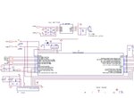
  • Connection.jpg
    Connection.jpg
    122.3 KB · Views: 112
  • ecan normal.txt
    34.4 KB · Views: 115

@bigdog
Hi,
In the program, when run in normal mode, TXREQ0 bit is always set and transmission is not happeneing.
Please tell me how can I correct it and a successful communication can be made...
 

Hi,
This is what happening when I try to transmit.
For transmission, I will set the TXREQ0 bit to trigger the DMA transfer. The DMA tries to transfer the data and DMA0IF is set. But the TXREQ0 remains set and IVRIF flag is set and TBIF is not being set. Means, the transmission is trying to takeplace but some error is happening due to which the TBIF flag is not set. This happens even if I don't connect it to the external bus. But if I don't connect the transceiver to the controller, IVRIF flag won't be set but TXREQ0 will be set.
Hope some one could help me...
please help...
 

Hi everybody,
I found my problem. It was due to the fault in the transceiver connected to one of the controller. I changed the controller and now its working fine. I am able to communicate between the microcontroller... :) :) :)
Thanks for the help you all offered...
 

hi now you can upload steps u follow while initializing that u r in which mode while initilizing and which mode is use to where and basic of can protocol to run on controller.
thanx.
 
hello if i have CAN TxRx of Texas Instrument and using can controller of PIC that is consider as any 18F series then my question is wheather this communication will done or not.
 

Hi embpic,
I'm not sure of your scenario. I'm not an expert in CAN implementation considering all types of micro-controllers. I'm not sure how it is done-whether it is the same way as being done on the dsPIC controller. What I know is to implement ECAN implementation in dsPIC microcontroller using MCP2551(which has only two pins to be connected to the controller as shown in the diagram). There are some other TxRx which uses three wires to connect to the controller. But I think it won't matter much considering the implementation.
I'm not sure of the procedure to be followed to implement CAN in 18F.
But in dsPIC what I have done, I can explian it to you.
Before start doing the initialisation of the CAN, it is very necessary to set the right baud rate for communicating with other devices. If you are using MPLab X IDE you could get a ecan baud rate calculator plugin to help with the situation.
Also for the CAN to work successfully you need to have atleast two working to node to get connected to the CAN bus to acknowldge the transmission of the TXr.
For configuring the CAN, you have to put the CAN module in the configuration mode which you can set by putting 0b100 in the REQOP field in the C1CTRL1 SFR. you set the remaining registers, configure the filtwers mask etc. and you can put the CAN module in to normal mode(000) the same way.
 

Microchip has some low cost CAN modules like MCP2515DM-BM. Start here and google for examples and code.
The Microchip kit contains 2 boards with pic18f4550 ,serial cable etc.

The cost of this kit is so low that you can't even buy the parts for the same amount....
 
Last edited:

Hi,
does anybody know how to recieve multiple frames continously in dsPIC33f ecan module?..
 

The following CAN example demonstrates how to use dsPIC's DMA to send and receive large multibyte messages, without the intervention of the CPU core:

AN1249 ECAN Operation with DMA on dsPIC33F and PIC24H Devices

AN1249 Source Code

OVERVIEW

The ECAN module works in conjunction with the DMA
controller in dsPIC33F and PIC24H devices. The DMA
controller is a very important subsystem in Microchip’s
high-performance 16-bit dsPIC33F and PIC24H
devices. The DMA controller allows data transfer from
RAM to a peripheral and vice versa without any CPU
assistance, and operates across its own data bus and
address bus with no impact on CPU operation.

The DMA subsystem supports eight independent
channels. Because each channel is unidirectional, two
channels must be allocated to read and write to the
ECAN peripheral using DMA. One channel is allocated
for reading messages from the ECAN peripheral and
the other channel is allocated for writing messages to
the ECAN peripheral.

When more than one DMA channel receives a
request to transfer data, a simple fixed-priority
scheme that is based on the channel number dictates
the specific channel that completes the transfer and
the channels that are left pending. Each channel has
a fixed priority. The channels with a lower number
have higher priority, with channel 0 having the highest
priority, and channel 7 having the lowest priority.

Each dsPIC33F or PIC24H device contains up to
2 Kbytes of Dual Port SRAM (DPSRAM), which is
adequate to concurrently support multiple buffers for
several peripherals. Figure 1 highlights the DMA
integration with the architecture of dsPIC33F and
PIC24H devices. The CPU communicates with
conventional SRAM across the data space X-bus
known as the CPU X-bus, as shown in Figure 1. It also
communicates to port 1 of the new dual port SRAM
block across the same X-bus.

The CPU communicates to the ECAN peripheral
across a separate peripheral data space bus known as
the CPU Peripheral X-bus, shown in Figure 1, which
also resides in the X data space. The DMA controller
communicates with port 2 of the dual port SRAM and
the DMA port of ECAN module across a dedicated
DMA transfer bus known as the DMA X-bus.

Another similar example:

CE171 - ECAN DMA Register Indirect Code Example for Standard Messages

BigDog
 
Hi Guys,

Sorry for digging this old post but its exactly what my current objective is. I'm in a similar situation of drafting a project where my logic is exactly as mentioned above.
At this stage I've got the liberty of using any MCU and components. The idea is to depict ECU conditions to control CAN run devices. Read/Write data to the devices with CAN protocol. I can easily do this by using Grid Connect's PCAN adapter and their software. My goal is to build something similar and universal. What their software does is connect with the device(PCAN adapter) and starts transmitting 8bits, each bit containing different msg or error code. On transmission side we can control the bits/device while on receiving end the device sends out error codes.

My aim is to build a stand alone MCU unit that does all of this. My proficiency and comfort of coding is MikroC because of their pre-built libraries. The plan is to design something that hooks up with a CAN protocol device, handshakes and can be controlled by I/Os(buttons, nobs, touch panel etc) the error codes displayed on an LCD and as an added feature data transmitted via bluetooth, zigbee or WiFi.

If a step by step guide is provided then this process can be made fun and informative. Looking forward for feedback.

Cheers.
 

Status
Not open for further replies.

Part and Inventory Search

Welcome to EDABoard.com

Sponsor

Back
Top