Continue to Site

Welcome to EDAboard.com

Welcome to our site! EDAboard.com is an international Electronics Discussion Forum focused on EDA software, circuits, schematics, books, theory, papers, asic, pld, 8051, DSP, Network, RF, Analog Design, PCB, Service Manuals... and a whole lot more! To participate you need to register. Registration is free. Click here to register now.

Problem using MTEE microstrip line in an equal split wilkinson power divider

Status
Not open for further replies.

Kuangyuan Ying

Newbie level 2
Joined
Jun 20, 2013
Messages
2
Helped
0
Reputation
0
Reaction score
0
Trophy points
1
Activity points
17
Hi,

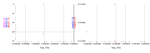
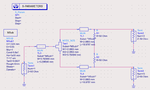
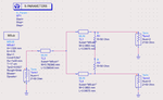
I am designing an equal split wilkinson power divider working at 13GHz in ads. When i add a MTEE to it, the s-parameter all goes wrong. I think i may have used the MTEE in a wrong way. Could someone help me with that?
Attached are the schametic and s-parameter simulation results

:roll::roll:

Thanks so much.
 

Attachments

  • wilkinson3.png
    wilkinson3.png
    22.7 KB · Views: 171
  • wilkinson2.png
    wilkinson2.png
    110.3 KB · Views: 167
  • wilkinson1.png
    wilkinson1.png
    95.5 KB · Views: 155

When you add the MTEE you would certainly need to adjust the MLIN lengths (usually shorten) to compensate for the length of the MTEE. However, you have increased the length from 3.39575 mm to 16.9787 mm between the two designs. This doesn't look right. Please verify these numbers. There is nothing wrong with the configuration of the MTEE itself.

Also really you should be looking at mag(S(2,1)) and mag(S(3,1)) instead of mag(S(1,2)) and mag(S(1,3)) but that should be symetrical. Also I would want to look at the swept frequency data to be sure that the design was centered.
 
you should optimize the lengths of the two arms to get the max isolation at midband.

Also, Mtee is good start, but u also need a microstrip 90 degree bend in both arms too.

You should know that adding and Mtee to a Microstrip bend model so close together will, invariably, violate the rules those structures were modeled under, and give erroneous results. You should follow up with an emag simulator analysis for a final tweek

Also, u are not really using two 50 ohm resistors in series are you? a bad idea.

use a 100 ohm single chip like this one:
**broken link removed**
 
I changed because i though maybe a quart-wavelength line is too short so that adding a mtee would affect the length seriously.So i used a 5/4 waveleng line.
I just shorten the two lines for half of the value of w3. the s22 and s33 looks better, but the s11 and the s31,s21 still no good.
Is it because something wrong with the connection between the first 50-ohm line and the TEE?
The sweep is single point at 13GHz.
wilkinson4.png
By the way, THanks for the reply.
 

So the input transmission line calculates out as a 50ohm line of lamda/4 in length but take a look at the actual dimensions. It is wider, more than lamba/4, than it is long. Similarly the 70ohm lines are getting close to lamda/4 wide. These are no longer a transmission lines. You really need to reconsider the board material. It will never work as you expect at 13Ghz and 1.5mm thick. You would never be able to create a practical layout for this design. You need to use a much thinner material at that Er so that the dimensions become more realistic.
 

Status
Not open for further replies.

Part and Inventory Search

Welcome to EDABoard.com

Sponsor

Back
Top