Continue to Site

Welcome to EDAboard.com

Welcome to our site! EDAboard.com is an international Electronics Discussion Forum focused on EDA software, circuits, schematics, books, theory, papers, asic, pld, 8051, DSP, Network, RF, Analog Design, PCB, Service Manuals... and a whole lot more! To participate you need to register. Registration is free. Click here to register now.

Question for a circuit …

Status
Not open for further replies.

Achelius

Newbie level 6
Joined
Aug 9, 2011
Messages
11
Helped
3
Reputation
6
Reaction score
3
Trophy points
1,283
Activity points
1,352
Hello from Greece !!!

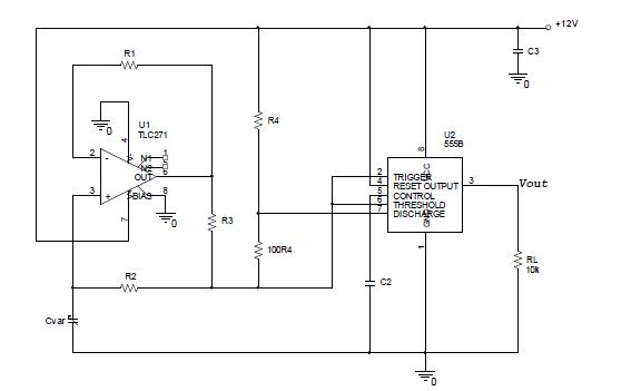
In this circuit, the variable air capacitor Cvar is used as a converter angular position in frequency

I need a small help for this a circuit. Can someone explain to me what job makes the amplifier of figure? Is it Wien bridge oscillator ? Function generator ? Is it something else ? What

Thank you !!!


@Achelius:Where is input to your circuit.I can only see supply voltage of +12V.
 
I assume the variable capacitor is the 'input'. It looks like a square wave relaxation oscillator.

Keith
 
i believe the circuit is wronk. No right. The feeback circuit of R2 and R3 must been placed at non inverting input of operational amplifier (3 pin) and not at pin 2 (inverting input
 

@Achelius: Shouldn't the variable capacitor be connected to inverting terminal(pin 2) keeping the feedback resistor R2 as it is and removing R3 & connect it from non-inverting terminal to ground so that it operates in positive feedback.

Then you will see a saw-tooth kind of wave at inverting input & square-wave at the o/p node.
Capture.JPG
 
Last edited:
The block corresponding to the operational amplifier is a capacity multiplier.

The 555's block is the traditional astable oscillator working with the capacitor "multiplied".
 
but where is the input of the circuit and hοw this works ?
 

There is no "input" - as you said yourself,
the variable air capacitor Cvar is used as a converter angular position in frequency
.

I am not sure it actually would work. rahdirs' suggestion looks good, although you might need to bias the resistors to the non-inverting input to be nominally mid rail if you want it to work off a single rail.

Keith
 
These circuits are proposed from the manual of LM108. What is your opinion ? Are they functional ?

circuit111.JPG
 

These circuits are proposed from the manual of LM108. What is your opinion ? Are they functional ?

Why not? The last circuit is the multiplier adopted in your schematic.

The need for a capacitance multiplier is because the capacitor formed by the plates which you senses the angle is of a few picofarads.
 
For this circuit. Can someone explain the meaning of the expression "slope conversion 40 Hertz per Degree (angle)"?

Do you know the right equation?


Status
Not open for further replies.

Part and Inventory Search

Welcome to EDABoard.com

Sponsor

Back
Top