Welcome to our site! EDAboard.com is an international Electronics Discussion Forum focused on EDA software, circuits, schematics, books, theory, papers, asic, pld, 8051, DSP, Network, RF, Analog Design, PCB, Service Manuals... and a whole lot more! To participate you need to register. Registration is free. Click here to register now.
Don’t carry on so, you are wrong. Topic starter got my code (not yours) with 7MC per sample (post #17). It means that sampling frequency is 20000kHz/7=2857ksps. In other words, if TC needs to produce 1MHz output signal, then aliasing frequency is 1857kHz, far enough to easily get rid of it. Eng.Fahd can use the interruption for tuning any frequency in range 0.17Hz to 1000000 Hz. That's all.
I want to ask you George.
In a 1 MHz generation, the output samples will be just 2. I mean the signal will be like a square signal. So I need you to give me the right filter that I can use in my project to work from Hz to MHz.
Thank you kripacharya for interest in helping me, and thanks to GeorgeM.
And I'm sorry because this little problem goes in this way of misunderstanding.
I want to ask you George.
In a 1 MHz generation, the output samples will be just 2. I mean the signal will be like a square signal. So I need you to give me the right filter that I can use in my project to work from Hz to MHz.
actually it will be 2.857 output samples per cycle.
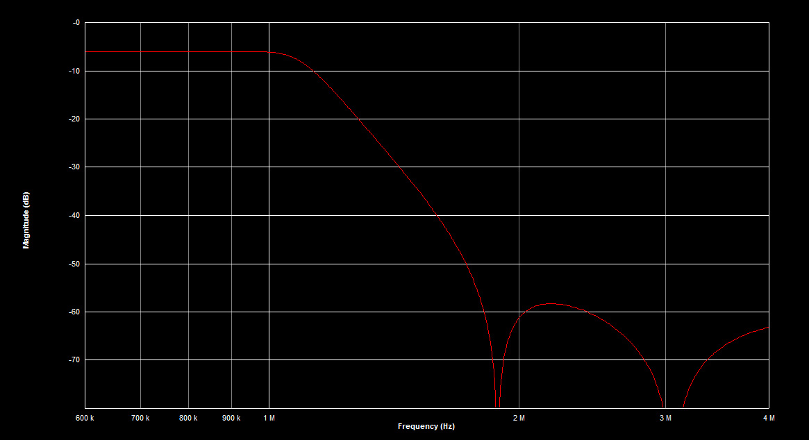
The image freq will be at 1.857 MHz ( 2.857M - 1M)
You need a LPF for 1MHz - 1.857MHz.
Here is a possible filter you can use. It is designed for 0.1dB passband ripple and >50dB attenuation at 1.84MHz. Note that input/ output impedance is 50ohm, and insertion loss of filter is 6dB (i.e. voltage will be half of input)
It uses only 2 inductors of lowish value and Q ~70, which is helpful since a lot of design sensitivity is due to inductors.
This site uses cookies to help personalise content, tailor your experience and to keep you logged in if you register.
By continuing to use this site, you are consenting to our use of cookies.
")