Continue to Site

Welcome to EDAboard.com

Welcome to our site! EDAboard.com is an international Electronics Discussion Forum focused on EDA software, circuits, schematics, books, theory, papers, asic, pld, 8051, DSP, Network, RF, Analog Design, PCB, Service Manuals... and a whole lot more! To participate you need to register. Registration is free. Click here to register now.

[SOLVED] Help with generating sinewave

Status
Not open for further replies.

Eng.Fahd

Junior Member level 3
Joined
Aug 17, 2011
Messages
25
Helped
4
Reputation
8
Reaction score
4
Trophy points
1,283
Visit site
Activity points
1,467
I want to generate a sinewave with variable frequency (from Hz to 1 MHz) using microcontroller.... First I used DDS method and it worked but I couldn't reach to 1 MHz ... so this method didn't work .... Then I found IC's like max038 which generate sinewave but I don't want to use them ....
I think I can use microcontroller to generate square wave and then I will convert it to sine wave (I think using a filter)... so I want your help in this step ....
because for 1 MHz I don't know if I can convert this signal using a filter ....
And should I use many filters for the variable values of frequency of sine wave....
Any help, or new ideas or suggestion ...

Thanks.....
 

Filtering a square-wave to get a low distortion sinewave requires a high order filter and it is very difficult to vary their frequency so I don't think that's a viable scheme.

You might consider a DDS chip such as one of these.
 
Thank you.... I know that DDS chip ,.. I got my answer that I can't generate my sine wave using square wave and a filter ... thanks again .
 

A good solution is the so-called "coupled-form oscillator".
As a bonus, it has two outputs in phase quadrature.
It can be viewed as a 2nd order filter with the poles in the unit circle.
See for example the book "Digital Signal Processing" (3rd Ed.) by Proakis and Manolakis.
Regards

Z
 
I want to generate a sinewave with variable frequency (from Hz to 1 MHz) using microcontroller.... First I used DDS method and it worked but I couldn't reach to 1 MHz ... so this method didn't work

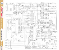
Here we are: **broken link removed** Specs: MC ATtiny2313, 20 MHz quartz, Fsampling=2222ksps, output frequency [0.1 Hz-1000 kHz], you need LF-filter 0-1000 kHz, an encoder tunes the frequency with 0.1 Hz, 1 Hz, 100 Hz, 1 kHz and 10 kHz steps. Peculiarity: the output signal is not interrupted during the tuning.
 
Last edited:
Here we are: **broken link removed** Specs: MC ATtiny2313, 20 MHz quartz, Fsampling=2222ksps, output frequency [0.1 Hz-1000 kHz], you need LF-filter 0-1000 kHz, an encoder tunes the frequency with 0.1 Hz, 1 Hz, 100 Hz, 1 kHz and 10 kHz steps. Peculiarity: the output signal is not interrupted during the tuning.

Thanks GeorgeM, but when I try to download the firmware then site give me this message (На сервере проводятся технические работы. Сервер будет доступен в течение 48 часов.)
Can you give an available link of the circuit board and firmware.
 

here is a link to a popular and very simple DDS with full details, which is the same as the russian one i suspect...

**broken link removed**

You can theoretically get 1MHz with this using a 20MHz crystal, but the number of points on your highest freq will be only 2.2 per cycle. Also since the sampling freq is 2.2Mhz then the image will be at 1.2Mhz, and almost impossible to filter.

you can try to increase the sampling freq by shifting the LUT to SRAM instead of Flash. This gives an additional benefit of 1 cpu cycle per 9 cycles or a speed increase upto 2.5Mhz
sacrificing frequency resolution by 8 bits will add another 2 cycles to give you 3.3MHz. Overclocking the uc or using a PIC at a higher frequency with the same basic algorithm might help.

with a properly designed and well implemented 5-pole or 7-pole LPF on the output you could get a fairly decent high frequency output. But it won't be great.
Also at the higher end, you have to look out for the sin(x)/x amplitude droop.
 
Thanks GeorgeM, but when I try to download the firmware then site give me this message (На сервере проводятся технические работы. Сервер будет доступен в течение 48 часов). Can you give an available link of the circuit board and firmware.

1) It means "The site under reconstruction for 48 hours". Try it again.
2) The schematic was taken from **broken link removed**. I’ve only added 20 MHz quartz with 22 pF capacitors and encoder in lieu of "+"/"-" buttons.
3) Find the attached file dds24plc.zip

- - - Updated - - -

here is a link to a popular and very simple DDS with full details, which is the same as the russian one i suspect...
You can theoretically get 1MHz with this using a 20MHz crystal, but the number of points on your highest freq will be only 2.2 per cycle.
Also since the sampling freq is 2.2Mhz then the image will be at 1.2Mhz, and almost impossible to filter.
you can try to increase the sampling freq by shifting the LUT to SRAM instead of Flash. This gives an additional benefit of 1 cpu cycle per 9 cycles or a speed increase upto 2.5Mhz
with a properly designed and well implemented 5-pole or 7-pole LPF on the output you could get a fairly decent high frequency output. But it won't be great.
Also at the higher end, you have to look out for the sin(x)/x amplitude droop.

1) Jensen DDS is the similar one but not the same. As I said my DDS is able to produce the output signal when you turn the encoder. It gives you the beauty sense of belonging to the analogue world.
2) It doesn’t matter how many samples per period you have because the second harmonic is too far (2 MHz). The image is more dangerous, but for 1 MHz signal its frequency is 1.22 MHz that gives us 220/1000 = 22% of the whole band. You need to attenuate it for 40-50 dB, it isn’t so easy but you can still do it. Also the filter can correct the amplitude sin(x)/x fall.
3) Attiny2313 has 128 byte ram only, so you cannot reduce the number of cycles less than 9 for 24-bit phase accumulator. Especially for Jesper I’d reduced it to 8 cycles per sample and sent him email. But even with 8 cycles per sample (2.5 Msamples/s) my own DDS can still accept the tuning commands from the encoder or through the RS232 line without interruption of the output signal. That’s main feature of my DDS.
 
Last edited:
Thanks..
George, I tried again but the site still show that message, And I didn't find the file dds24plc.zip . Can you give me a link on another upload center like mediafire or any available link,Please.
Thanks again.
 

1) Also the filter can correct the amplitude sin(x)/x fall.

i'd love to get the filter design which does both - image filter @1.2MHz and sinx/x compensation!! Can you post it ? A 7th order elliptic can do the 50dB, but how would you add the x/sin(x) modification ?

3) Attiny2313 has 128 byte ram only, so you cannot reduce the number of cycles less than 9 for 24-bit phase accumulator. Especially for Jesper I’d reduced it to 8 cycles per sample and sent him email.

thats true - i used a Atmega48 which has more ram.

But even with 8 cycles per sample (2.5 Msamples/s) my own DDS can still accept the tuning commands from the encoder or through the RS232 line without interruption of the output signal. That’s main feature of my DDS.

well of course the output signal will get interrupted !! It's just that @20MHz and 50nS per cycle, the isr (for uart or kbd) can be very small in comparison and the 'error' caused by it almost un-noticeable. I cannot see a way to avoid it - as you claim.
 
Last edited:
And I didn't find the file dds24plc.zip

Try this one.

- - - Updated - - -

well of course the output signal will get interrupted !! It's just that @20MHz and 50nS per cycle, the isr (for uart or kbd) can be very small in comparison and the 'error' caused by it almost un-noticeable. I cannot see a way to avoid it - as you claim.

No, it isn't allowed to make any disturbance in sample output timing (jitter). MC outputs samples exactly in every 450 ns (9MC-mashine cycle). Try the code below.
 

Attachments

  • dds24plc.zip
    2 KB · Views: 110
Last edited:
No, it isn't allowed to make any disturbance in sample output timing (jitter). MC outputs samples exactly in every 450 ns (9MC-mashine cycle). Try the code below.

are you serious ? you've posted a hex file... and claim that it isn't allowed to make any disturbance in sample output timing . I find that very very difficult to imagine, since the samples are calculated in a hard loop with no timing tolerances.

Are you saying that you can modify the phase vectors in zero cycles ? now that i would love to be able to do !!! LoL !
 

Especially for Jesper I’d reduced it to 8 cycles per sample and sent him email.

can you explain how you reduced it to 8 without the RAM ?

I know of a method to reduce it to 7 w/o extra RAM, and down to 6 with enough RAM.
and maybe even down to almost 3 with some additional trickey calculations


can you explain how you reduced it to 8 without the RAM ?
I know of a method to reduce it to 7 w/o extra RAM, and down to 6 with enough RAM.
and maybe even down to almost 3 with some additional trickey calculations
Good, if you can get 7MC, then it's very easy to get 8MC. Just add one NOP to your code :).
 

7 machine cycles per sample (**broken link removed**)

dds:
out portb,r13
add r11,r21
adc r12,r22
adc r30,r23
ld r13,z
add r11,r21
out portb,r13
adc r12,r22
adc r30,r23
ld r13,z
rjmp dds

kripacharya, I wonder what you’ll say now. What is dumb and who is silly?
 

Very clever code. Thanks !! Good way to divide the extra 2 cycles of the rjmp.

But i notice that you did use RAM despite your tall claims, so i'm not sure how you got 7 cycles w/o ram and tell me to add a NOP to get 8. That was my original question, and your answer doesn't sound so funny really.
 

Status
Not open for further replies.

Similar threads

Part and Inventory Search

Welcome to EDABoard.com

Sponsor

Back
Top