Continue to Site

Welcome to EDAboard.com

Welcome to our site! EDAboard.com is an international Electronics Discussion Forum focused on EDA software, circuits, schematics, books, theory, papers, asic, pld, 8051, DSP, Network, RF, Analog Design, PCB, Service Manuals... and a whole lot more! To participate you need to register. Registration is free. Click here to register now.

How to measure LM35 Negative Temperature

Status
Not open for further replies.
Joined
Jul 25, 2012
Messages
1,192
Helped
171
Reputation
342
Reaction score
162
Trophy points
1,343
Activity points
0
Hello!

I want to know how to measure temperatures in the range -55 degree C to +150 degree C using LM35

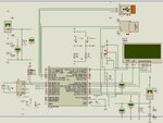
I amusing PIC18F46J50 pin RA0 and RA1. It has 10-bit ADC. my Vref is 1.87v. So, for 1.87v I get 1023 raw adc value. I have configures the ADC properly.

I am getting right values for the range 0-150 degree C, but 0- -55 degree C is giving wrong values

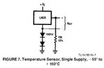
I have used the attached circuit given National Semiconductor's LM35 datasheet

I got 1007.999 raw value and 186.9999 raw value for the two channels at 150 degree C.

So, I subtracted 186.9999 from 1007.999 to get 820.9991

for 150 it is 820.9991 raw value. So, I did 150/820.9991 = 0.1827042197732007

I used 0.1827042197732007 value to multiply the temp - temp1 raw adc values.

I am getting right values for 0-150 degree C range, but negative temperature is giving wrong values.


Thanks
Jayanth D
 

Attachments

  • f9e1kh (1).jpg
    f9e1kh (1).jpg
    8.3 KB · Views: 392

Here is the project file. The project uses usb hid communication. put the mcHID.dll file in windows\system32 folder and compile the mikroC Pro code for 20MHz.
VB.Net 7 Scales.rar is complete. Install the file by running setup.exe

Thanks
Jayanth D
 

Attachments

  • RTC ADC SD Datalogger FvM.rar
    192.1 KB · Views: 222
  • mcHID.rar
    136.1 KB · Views: 134
  • vb.net app.rar
    182.9 KB · Views: 117
  • VB.Net 7 Scales.rar
    183 KB · Views: 138
Last edited:

Before diving into the project, I would appreciate an answer to my simple question.

LM35 is specified to work with negative temperatures. Either the respective output voltages don't arrive correctly at your ADC, or it's a trivial arithmetic problem with negative numbers. By seeing the ADC values and results for negative temperatures, you can easily sort out one or the other.
 
What arithmetic should I use for LM35 negative temperatures. There is no formula given in LM35 datasheet.
 

The formula is 10mV/C, exactly the same as for positive values.

The output of the LM35 needs to be pulled negative with respect to it's ground pin to measure below 0C. You are doing this by raising the ground pin above zero volts which is fine. This means a zero output from the LM35 will read as 2*Vf of the diodes in the ground pin and you must subtract that to normalize the measurement. For best accuracy, take two voltage measurements, one from the grund pin so you know exactly what 2*Vf is, the other from the LM35 output. These can only be positive votages so they are easy to read with an ADC. Subtract the ground pin measurement from the output measurement and you have the temperature.

If the math still doesn't work (I haven't chedked your code) make sure you are not using unsigned variables so you can handle negative numbers.

All this reminds me why I switched to using MCP9701A to measure temperature - no subtracting and an output scaled to suit an ADC :)

Brian.
 
I agree with FvM, look into the datasheet maybe the ADC is giving 2's complement for the negative values, for most of the ADCs we need to make some kind of conversion to get the exact negative value, so just be sure whether you are doing your conversions right i feel that its just a small conversion error as you have already said that it works fine with 0 to +150 C.

Moreover this has got nothing to do with the LM35, so don't look into the datasheet of LM35 for any formula, you need to look into the ADC datasheet.
 
@betwixt

What is 2*Vf of the diodes in the ground pin? Is it 2 * forward voltage? How to calculate it?

You say that "For best accuracy, take two voltage measurements, one from the ground pin so you know exactly what 2*Vf is, the other from the LM35 output."

Is my circuit wrong? I know the LM35 output and that will be one of the adc inputs. Where should I connect the another adc input.


My code is like this, channel 0 is the LM35 output. channel 1 is the other output at LM35.
Code:
temp = ADC_Read(0);
temp2 = ADC_Read(1);
temp = temp - temp2;

Jayanth D
 

Vf depends on the type of diode you use but for a 'normal' silicon signal diode like the 1N914 it should be around 0.6V so for two in series it will be around 1.2V. You should be aware that Vf of a diode changes slightly with temperature, that's why I suggest using one input of the ADC to read the actual voltage rather than relying on it being 1.2V.

The circuit is correct, as long as you have an ADC reference voltage higher than the LM35 will ever produce. Most procesors with on-board ADCs will let you choose ground (VSS) as the low reference and supply (VCC or VDD) as the high reference which will ensure you are always within safe limits.

If you can read 'temp' and 'temp2' you should find 'temp2' (Vf) is a fairly stable voltage around 1.2V and 'temp' (output) is above or below it depending on the temperature. At 0C, the two should be the same. Note that these are both positive voltages, they never go negative. If they did the ADC wouldn't be able to read them anyway.

Your calculation should return the LM35 output voltage minus the LM35 ground in voltage, in other words the voltage the LM35 is producing. There is only one output on the LM35.

You haven't shown how you declare these variables and this may be part of your problem. To be able to handle a value of 0 to 1023, two bytes are needed so (assuming you are using an 8-bit processor) they must be declared as "unsigned int". If you have them as type "char" or "int" you will get strange results because the subtraction may leave the most significant bit set which would reverse the polarity of the result.

Brian.
 
@betwixt

I am getting 0.34v Vf for 150 degree C and my Vref is 1.87v and I am getting 1.85v at LM35 output for 150 degree C. I have attached an image. You can see the values.

The problem is for 0 degree C I am getting Vf as 0. How to solve the problem. I am using double type for the temp (LM35 o/p) and temp2 (Vf) variables.

I am posting the code. Please have a look at it and tell me where I am going wrong? Is it hardware problem? I am using mikroC Pro.

Should I give a voltage of 1.2 to RA1 pin that is 2nd adc channel instead?

Code:
unsigned char Read_Buffer[64] absolute 0x500;
unsigned char Write_Buffer[64] absolute 0x541;
unsigned char num,flag;

#ifndef DS1307
        #define DS1307 0xD0
#endif

#define SW5MINS PORTD.F2
#define SW30MINS PORTD.F3

// LCD module connections
sbit LCD_RS at LATB0_bit;
sbit LCD_EN at LATB1_bit;
sbit LCD_D4 at LATB2_bit;
sbit LCD_D5 at LATB3_bit;
sbit LCD_D6 at LATB6_bit;
sbit LCD_D7 at LATB7_bit;

sbit LCD_RS_Direction at TRISB0_bit;
sbit LCD_EN_Direction at TRISB1_bit;
sbit LCD_D4_Direction at TRISB2_bit;
sbit LCD_D5_Direction at TRISB3_bit;
sbit LCD_D6_Direction at TRISB6_bit;
sbit LCD_D7_Direction at TRISB7_bit;
// End LCD module connections

void Hid_Enable(char *Read_Buffer, char *Write_Buffer);
char HID_Write(char *Write_Buffer, char len);

char x;                              // Loop variable
int cnt;

double temp, temp2;
char sTemp[23], sTemp2[23];

char colon[] = ":";

char i;
unsigned char sec, min1, hr, week_day, day, mn, year;
char *txt, tnum[4];
int am_pm = 0;
char time_format[3];
unsigned long int usb_tx_cnt_val, usb_tx_cnt = 0;
bit usb_tx_flag;


void interrupt()
{

  usb_tx_cnt++;
 USB_Interrupt_Proc();
 if(usb_tx_cnt == usb_tx_cnt_val) {
    usb_tx_flag = 1;
 }
 TMR0L = 100;             //Reload Value
 INTCON.TMR0IF = 0;       //Re-Enable Timer-0 Interrupt
}

void clear_buffer(unsigned char buffer[])
{
 unsigned int x = 0;
 while(buffer[x] != '\0')
 {
  buffer[x] = '\0';
  x++;
 }
}

void Zero_Fill(char *value) {
        if (value[1] == 0) {
                value[1] = value[0];
                value[0] = 48;
                value[2] = 0;
        }
}

void Write_Time() {
        I2C2_Start();          // issue start signal
        I2C2_Wr(DS1307);       // address DS1307
        I2C2_Wr(0);            // start from word at address (REG0)
        I2C2_Wr(0x80);         // write $80 to REG0. (pause counter + 0 sec)
        I2C2_Wr(0);            // write 0 to minutes word to (REG1)
        I2C2_Wr(0x17);         // write 17 to hours word (24-hours mode)(REG2)
        I2C2_Wr(0x02);         // write 2 - Monday (REG3)
        I2C2_Wr(0x04);         // write 4 to date word (REG4)
        I2C2_Wr(0x05);         // write 5 (May) to month word (REG5)
        I2C2_Wr(0x01);         // write 01 to year word (REG6)
        I2C2_Stop();           // issue stop signal

        I2C2_Start();          // issue start signal
        I2C2_Wr(0xD0);         // address DS1307
        I2C2_Wr(0);            // start from word at address 0
        I2C2_Wr(0);            // write 0 to REG0 (enable counting + 0 sec)
        I2C2_Stop();           // issue stop signal
}

void Read_Time(char *sec, char *min, char *hr, char *week_day, char *day, char *mn, char *year) {
        I2C2_Start();
        I2C2_Wr(DS1307);
        I2C2_Wr(0);
        I2C2_Repeated_Start();
        I2C2_Wr(0xD1);
        *sec =I2C2_Rd(1);
        *min =I2C2_Rd(1);
        *hr =I2C2_Rd(1);
        *week_day =I2C2_Rd(1);
        *day =I2C2_Rd(1);
        *mn =I2C2_Rd(1);
        *year =I2C2_Rd(0);
        I2C2_Stop();
}

void Transform_Time(char  *sec, char *min, char *hr, char *week_day, char *day, char *mn, char *year) {
        *sec  =  ((*sec & 0x70) >> 4)*10 + (*sec & 0x0F);
        *min  =  ((*min & 0xF0) >> 4)*10 + (*min & 0x0F);
        *hr   =  ((*hr & 0x30) >> 4)*10 + (*hr & 0x0F);
        *week_day =(*week_day & 0x07);
        *day  =  ((*day & 0xF0) >> 4)*10 + (*day & 0x0F);
        *mn   =  ((*mn & 0x10) >> 4)*10 + (*mn & 0x0F);
        *year =  ((*year & 0xF0)>>4)*10+(*year & 0x0F);
}

void Display_Time(char sec, char min, char hr, char week_day, char day, char mn, char year) {

        Lcd_Out(1,1,"Date:");

        switch(week_day){
                case 1: txt="Sun"; break;
                case 2: txt="Mon"; break;
                case 3: txt="Tue"; break;
                case 4: txt="Wed"; break;
                case 5: txt="Thu"; break;
                case 6: txt="Fri"; break;
                case 7: txt="Sat"; break;
        }
        Lcd_Out(1,7,txt);
        Lcd_Chr(1,11,(day / 10)   + 48);    // Print tens digit of day variable
        Lcd_Chr(1,12, (day % 10)   + 48);    // Print oness digit of day variable
        Lcd_Chr(1,13,'/');
        Lcd_Chr(1,14,(mn / 10) + 48);
        Lcd_Chr(1,15,(mn % 10) + 48);
        Lcd_Chr(1,16,'/');
        Lcd_Out(1,17,"2");
        Lcd_Out(1,18,"0");
        Lcd_Chr(1,19, (year / 10)  + 48);          // Print year vaiable + 8 (start from year 2008)
        Lcd_Chr(1,20, (year % 10)  + 48);

        if(hr >= 12) {
           Lcd_Out(2,7,"PM");
           am_pm = 1;
        }
        else if(hr < 12) {
           Lcd_Out(2,7,"AM");
           am_pm = 0;
        }

        Lcd_Chr(2,11,(hr / 10)  + 48);
        Lcd_Chr(2,12,(hr % 10)  + 48);
        Lcd_Out(2,13,":");
        Lcd_Chr(2,14,(min / 10) + 48);
        Lcd_Chr(2,15,(min % 10) + 48);
        Lcd_Out(2,16,":");
        Lcd_Chr(2,17,(sec / 10) + 48);
        Lcd_Chr(2,18,(sec % 10) + 48);

}

void load_Write_Buffer() {

      if(am_pm == 1) {
            time_format[0] = 'P';
            time_format[1] = 'M';
      }
      else if(am_pm == 0) {
            time_format[0] = 'A';
            time_format[1] = 'M';
      }

      Write_Buffer[0] = 'D';
      Write_Buffer[1] = 'a';
      Write_Buffer[2] = 't';
      Write_Buffer[3] = 'e';
      Write_Buffer[4] = ':';
      Write_Buffer[5] = ' ';
      Write_Buffer[6] = txt[0];
      Write_Buffer[7] = txt[1];
      Write_Buffer[8] = txt[2];
      Write_Buffer[9] = ' ';
      Write_Buffer[10] = (day / 10)   + 48;
      Write_Buffer[11] = (day % 10)   + 48;
      Write_Buffer[12] = '/';
      Write_Buffer[13] = (mn / 10) + 48;
      Write_Buffer[14] = (mn % 10) + 48;
      Write_Buffer[15] = '/';
      Write_Buffer[16] = '2';
      Write_Buffer[17] = '0';
      Write_Buffer[18] = (year / 10)  + 48;
      Write_Buffer[19] = (year % 10)  + 48;
      Write_Buffer[20] = ' ';
      Write_Buffer[21] = 'T';
      Write_Buffer[22] = 'i';
      Write_Buffer[23] = 'm';
      Write_Buffer[24] = 'e';
      Write_Buffer[25] = ':';
      Write_Buffer[26] = ' ';
      Write_Buffer[27] = (hr / 10)  + 48;
      Write_Buffer[28] = (hr % 10)  + 48;
      Write_Buffer[29] = ':';
      Write_Buffer[30] = (min1 / 10) + 48;
      Write_Buffer[31] = (min1 % 10) + 48;
      Write_Buffer[32] = ':';
      Write_Buffer[33] = (sec / 10) + 48;
      Write_Buffer[34] = (sec % 10) + 48;
      Write_Buffer[35] = ' ';
      Write_Buffer[36] = time_format[0];
      Write_Buffer[37] = time_format[1];
      Write_Buffer[38] = 'T';
      Write_Buffer[39] = 'e';
      Write_Buffer[40] = 'm';
      Write_Buffer[41] = 'p';
      Write_Buffer[42] = 'e';
      Write_Buffer[43] = 'r';
      Write_Buffer[44] = 'a';
      Write_Buffer[45] = 't';
      Write_Buffer[46] = 'u';
      Write_Buffer[47] = 'r';
      Write_Buffer[48] = 'e';
      Write_Buffer[49] = ':';
      Write_Buffer[50] = ' ';
      cnt = 51;
      for(cnt=51;cnt<59;cnt++) {
          Write_Buffer[cnt] = sTemp[cnt-51];
      }
      Write_Buffer[60] = ' ';
      Write_Buffer[61] = '0';

}

void main() {
     TRISA = 0b00000011;
     PORTA = 0x00;
     LATA = 0x00;
     TRISB = 0b00000000;
     PORTB = 0x00;
     LATB = 0x00;
     TRISD = 0b00001111;
     LATD = 0b00000000;
     PORTD = 0b00000000;
     TRISC = 0x00;
     PORTC = 0x00;
     LATC = 0x00;
     ANCON0 = 0b11111100;
     ANCON1 = 0b10011100;
     ADCON0 = 0b00000000;
     //ADCON1 = 0b10110101;
     ADCON1 = 0b10110101;
     //CONFIG3H = 0b00001010;

     CM1CON.CON = 0;
     CM2CON.CON = 0;

     INTCON = 0;
     INTCON2 = 0xF5;
     INTCON3 = 0xC0;
     RCON.IPEN = 0;
     PIE1 = 0;
     PIE2 = 0;
     PIR1 = 0;
     PIR2 = 0;

     T0CON = 0x47; // Prescaler = 256  0b01000111
     TMR0L = 100; // Timer count is 256-156 = 100
     INTCON.TMR0IE = 1; // Enable T0IE
     T0CON.TMR0ON = 1; // Turn Timer 0 ON
     INTCON = 0xE0; // Enable interrupts

     cnt = 0;
     usb_tx_flag = 1;
     usb_tx_cnt_val = 38146;
     usb_tx_cnt = 0;
     Write_Buffer[62] = '1';
     Write_Buffer[63] = '1';
     Delay_ms(10);
     
     Lcd_Init();
     Lcd_Cmd(_LCD_CLEAR);
     Lcd_Cmd(_LCD_CURSOR_OFF);
     Lcd_Out(1,1,"RTC And Temperature");
     Lcd_Out(2,1,"Data Logger");
     I2C2_Init(100000);
     Hid_Enable(&Read_Buffer,&Write_Buffer);
     Delay_ms(2000);
     Lcd_Cmd(_LCD_CLEAR);
     txt = "Time:";
     Lcd_Out(2,1,txt);
     Lcd_Out(3,1,"Temp:");
     ADC_Init();
     
     while(1) {
         //Write_Time();
         Read_Time(&sec,&min1,&hr,&week_day,&day,&mn,&year);      // read time from RTC(DS1307)
         Transform_Time(&sec,&min1,&hr,&week_day,&day,&mn,&year); // format date and time
         Display_Time(sec, min1, hr, week_day, day, mn, year);

         temp = ADC_Read(0);
         temp2 = ADC_Read(1);
         temp = temp - temp2;
         temp = temp * 0.1827042186019435;
         FloatToStr(temp, sTemp);
         Lcd_Out(3,7,sTemp);
         

         if(usb_tx_flag == 1) {
               load_Write_Buffer();
               while(!HID_Write(&Write_Buffer,64));
               Write_Buffer[62] = '0';
               Write_Buffer[63] = '0';
               usb_tx_flag = 0;
               usb_tx_cnt = 0;
         }

         if(SW5MINS == 1) {
            Delay_ms(30);
               if(SW5MINS == 1) {
                    usb_tx_cnt_val =  38146;
                    usb_tx_cnt = 38145;
                    Write_Buffer[63] = '1';
               }
         }

         if(SW30MINS == 1) {
            Delay_ms(30);
               if(SW30MINS == 1) {
                    usb_tx_cnt_val =  228876;
                    usb_tx_cnt = 228875;
                    Write_Buffer[63] = '2';
               }
         }


     }
}
 
Last edited:

Lets check we are measuring the same voltages before going further:

All voltages should be measured from VSS, this is the ground (-) line.

Vf is measured at the 'gnd' pin of the LM35 where it connects to the top of the two diodes.
LM35 output is measured at the 'output' pin of the LM35
Vref is the reference voltage of the ADC.

Vf should be higher than 0.34V, ideally around 1.2V. If it's only 0.34V you can't measure temperatures below -34 degrees.
I'll make a suggestion, it might not work but it will prove a point, can you add a resistor of about 47K (not critical) across the LM35 between the 'gnd' pin and its suppy pin(Vs+). It may be that the input current drawn by the ADC is too high compared to the current passing through the LM35 and this is making Vf lower than it should be. The resistor will help to provide current through the diodes and might lift Vf up to it's proper voltage.

Questions: Where does Vref come from and what type of PIC are you using?

Brian.
 
I am attaching my Schematic. Adding resistor didn't help.

- - - Updated - - -

I am attaching my Schematic. Adding resistor didn't help.

Here is my project file.

Vref comes from potential divider. Actually I am using AVdd and AVss for Vref. I am using PIC18F46J50ML
 

Attachments

  • schematic lm35.jpg
    schematic lm35.jpg
    195.3 KB · Views: 207

OK, there are a number of points:

1. You can't use a simple potential divider to drop 5V down to VDD to power the PIC. Use a regulator because changes in load current will make VDD change. Also decouple all power pins as described in the data sheet.
2. Add a 10uF capacitor from VDDCORE to ground. (see section 27.3 in the data sheet)
3. The LM35 needs at least 4V supply to cover the full temperature range, you are powering it from about 3.8V
4. Your schematic shows Vref unconnected but you do have it software configured correctly for VDD and VDD to be used as references.

Brian.
 
@betwixt

regarding 1

Where am I using simple potential divider to drop 5V down to VDD to power the PIC?

Is my chip working at 3.3V in proteus? can it work at 5v? If yes, how to change to 5v in proteus? I don't see power pins for PIC.

regarding 2

I have added a 10uf capacitor from VDDCORE to GND

regarding 3

I have attached an image. In that it shows that voltage across LM35 is 5v. How do you say that I am powering LM35 with 3.8v?

regarding 4

I am using AVdd and AVss for Vref. You can see the ADCON and ANCON register settings.

Now what else can be the problem?


Jayanth D
 

Attachments

  • lm35 ps.jpg
    lm35 ps.jpg
    433.1 KB · Views: 190

1. R8 and R9 divide the 5V down to the AVDD pin. AVDD and VDD (if there is one, depends on the package) should be stabilized at 3.3V. Vref is on pin 22 but your ADC is set to use supply and ground for reference anyway so pin 22 isn't being used.

The IC is only rated to run on 3.3V, using 5V supply WILL damage it. Some inputs are "5V tolerant" which means they can be connected to 5V without being damaged.

3. The supply to the LM35 is between pins 1 and 3. You have 5V on pin 1 but there should be 1.2V on pin 3 so the voltage across it is 3.8V. It will work on 3.8V but it won't be able to read high temperatures.

4. The program configures Vref- to be ground and Vref+ to be VDD so in theory, with a 3.3V supply, each ADC step should be 3.3/1023 = 3.225mV.

I can't help with Proteus, I've never used it. I think you are seeing that a simulation is only as good as the information you give it. They never tell you what's wrong and often ignore things like wrong supply voltages.

Brian.
 

Status
Not open for further replies.

Part and Inventory Search

Welcome to EDABoard.com

Sponsor

Back
Top