Continue to Site

Welcome to EDAboard.com

Welcome to our site! EDAboard.com is an international Electronics Discussion Forum focused on EDA software, circuits, schematics, books, theory, papers, asic, pld, 8051, DSP, Network, RF, Analog Design, PCB, Service Manuals... and a whole lot more! To participate you need to register. Registration is free. Click here to register now.

Repairing Geiger Counter

Status
Not open for further replies.

Volka

Newbie level 4
Joined
Feb 23, 2005
Messages
7
Helped
0
Reputation
0
Reaction score
0
Trophy points
1,281
Activity points
1,379
Hi everybody! I hope this is the correct section for this...

I've recently gotten an Italian Geiger-Muller radiation counter. Judging by its look, I think it's from the 60s or 70s. The equipment says Misuratore di razioattivita MRG 310 DT SELO, Milano. I've goolged this information but there was no manual, no specification, nothing :(

So I'm on the dark here, trying to make it work. Actually the counter is in pretty good shape as far as I can tell. The ONLY thing is that there's one wire hanging and I don't have a clue where it's supposed to be connected to.

Here you can find some pictures:
**broken link removed**

The counter turns on without the cable, I've connected to +5 DC. The needle indicates battery status and kV (kiloVolts I assume) However I was unable to register any measurements. Alas I don't have any radioactive source (I've tried some rocks, and a banana...) but I'm planning to get a couple from a friend of mine. Nevertheless I think it's not working because it should detect some background radiation from time to time.

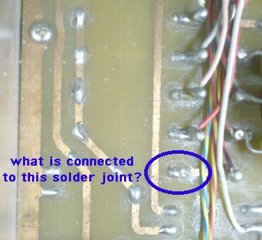
The wire comes from the selection knob. From the length of the cable I'm guessing it's going where I'm holding it on picture 4, but I'm not sure at all. I've tried to see if the was any indication of welding (or dewelding or whatever!) but I'm not seeing anything (I'm not an expert anyway). I could get some hi resolution close ups so that maybe you guys could help me out?

The oscillator that generates high voltage seems to work (I hear it buzzing) and I've measured like 300 V. The Geiger tube seems fine (forgot to take a picture!) but you never know with these oldies...

The meaning of the italian words are:
carica: charge
cuffia: headsets
spento: off
rete: AC line

Any ideas where that wire could go? Anything? :(

Thanks in advance guys!
 

I was able to see your pictures.

One of the radiation monitors I purchased off Ebay was a geiger counter which needed work. Victoreen 700-6A (or 6B). Made circa 1960 in large quantities for civil defense.

I finally got it going. I had to look over a number of manuals and schematics to figure out how the thing operates. Example:

**broken link removed**

I had to repair traces where battery ooze had corroded them.

Your unit has copper traces which have turned green with corrosion. Check across these areas for continuity.

The ONLY thing is that there's one wire hanging and I don't have a clue where it's supposed to be connected to.
...
The wire comes from the selection knob.

Look through about a 10x magnifying glass at the solder joints. Look for the ends of several tiny wires poking upward, that looks as though a wire broke off from it. That would be where the loose wire goes.

Look for any solder joint in the middle of a copper trace that doesn't appear to be needed at that position. That may be where your loose wire should go.

Your selector knob has many positions and many wires. If you compare your board with the schematic, you may spot a component which should connect to the selector knob, but has no wire going there.

The oscillator that generates high voltage seems to work (I hear it buzzing) and I've measured like 300 V.

This needs to be up near 900 or 1000V for the GM tube to fire when a particle goes through it. An aging tube often needs higher voltage than a new tube.

The high-V supply has high impedance. An ordinary multimeter has too low an impedance to give a correct reading. Even if it's a megohm it is liable to load the high-V supply. If available use a meter which has high input impedance. An FET-input meter is a possibility, but only if it can withstand 1000 V.

To find out if my GM tube worked, I made a voltage multiplier powered by house AC. I was able to use my oscilloscope to see it operate. To play it safe I gripped about a 10M resistor in the probe clip. I'm not sure I even needed to connect the ground wire.

-------------------------

To obtain radioactive samples to test with your geiger counter, an everyday source is to wipe the dust off a tv screen. Believe it or not, it is radioactive.

www.hps.org/publicinformation/ate/q157.html

Other sources:
* smoke detectors which contain americium
* a type of bright red plate called Fiestaware
* thorium mantle from a propane lantern
* an old-style glow-in-the-dark watch/clock containing radium paint.

https://www.blackcatsystems.com/science/radprod.html
 
Last edited:

Thanks a lot for your help, I'll do that and report :D

And yes the generator droped voltage as I tried to measure it with the multimeter so I wasn't able to get a clear reading. Unfortunately I don't have a high impedance multimeter.

Thanks again for all the information. About the tv screen you mean the old tvs with tubes right? I tried the oscilloscope screen with no results.
I knew about the americium inside smoke detector, I actually was thinking on buying one haha :D
 

I own a small Geiger tube myself, it needs around 500-600V. There's a 'plateau' there, a voltage range in which the Geiger tube has relatively constant behavior. Below that the voltage is too low to cause a cascade effect, too high and there will be arcing which might kill the tube (can also be killed instantly if polarity is connected the wrong way).

A high voltage source like this will have high output impedance so you can't measure it accurately with an ordinary multimeter. You could try loading it with a few different resistors (1-10MΩ range or so) with your multimeter in series, and measure output current. Plot that in a graph, and from that make a guesstimate what the 0-load voltage is.
 

About the tv screen you mean the old tvs with tubes right? I tried the oscilloscope screen with no results.
I knew about the americium inside smoke detector, I actually was thinking on buying one haha :D

Yes, the old CRT type.

As RetroTechie points out, your tube may work on a lower voltage than I quoted. Too high a voltage can ruin it or reduce its useful life.
 

So I've looking with a lens to see If I could spot anything funny with no luck. I did check continuity in the corroded pits.

When the geiger was given to me, the battery was taken out from where it's supposed to be fixed, so my guess is that the wire was in the way of the battery and the guy unplugged it so that he could take out the battery. So I've focused where the battery goes.

Maybe I have to get out of the box and look for other connections. Unfortunately I can't read the schematic you provided, it's not quite the same model. The knob is even too complicated to me to understand it :( The only thing I could get is that the outter copper layer is +Vcc and it's connected to the chassis (!).

Thank you for the information about how to measure the generator's output. I must confess it stress me to work with high voltages but if I'm brave enough I'd try to make a measurement :D

Since I can't figure out the wire thing this is what I'm going to do:
1)Get a piece of radioactive material, so I can know if the counter actually works as it is (maybe the wire just affects one scale!)
2)If it doesn't work, I'd like to test the geiger tube. In that regard BradtheRad, or anybody, if you have any more information about how to do it I'd appreciate it. I should also test the high DC voltage output.

What do you guys think about my plan? any suggestions?
More pictures: **broken link removed**

Oh oh I forgot about the headsets! I've added a picture where it shows the headset plug as I found it. It seems to me it's connected to the tube's ground mesh. How should I connect a speaker or headset in order to hear the "tac tac" (if it ever works!).
Also sorry about the cat she's so intrusive! At least she's not the one giving me an allergic reaction (the geiger counter stuff does, my eyes are irritated ha ha).

Thanks!
 

Back then I used an old tape recorder (configured as a simple audio amplifier) to translate current pulses from the Geiger tube into audible clicks.

In any case you'll need a high voltage source. Next, make sure there's a decent sized, good value resistor in series with the tube to make sure the current is limited to reasonable values at all times (order of magnitude: MΩ range). For simplicity's sake, regard the Geiger tube as a switch that closes for a µsecond or so (probably shorter?).

Then any additional series resistor will get a voltage spike over it according to the common R1/R2 voltage divider rule. You'd use that voltage as input for an audio amplifier (for example an active speaker from a PC would be fine, maybe a passive piezo speaker would do it too). And simply crank up the volume. :lol:

All you need is high voltage somewhere in the tube's 'plateau region' (varies per tube depending on size, gas mixture etc), and reasonable values for the series resistor(s). And patience - background radiation might be just a few particles hitting the tube a minute (perhaps even fewer, perhaps more depending on where you live & size of the tube).

But be careful what you use as 0V point, where the Geiger tube's HV is with respect to that, and polarity on the tube (see Wikipedia for example). If you are sure about the HV the tube needs, use that. If not 100% sure, I'd start around 500V or so, and see if you can squeeze out a response.
 

Unfortunately I can't read the schematic you provided, it's not quite the same model.

No, I didn't suppose the Victoreen schematic would match your unit. There could be other schematics on the internet. I had to look at several because there was an A and B schematic for mine.

Also check into discussion groups. I followed one on Yahoo for a while. It may still be there.

If it doesn't work, I'd like to test the geiger tube. In that regard BradtheRad, or anybody, if you have any more information about how to do it I'd appreciate it. I should also test the high DC voltage output.

Since it appears to have a built-in kV test, you may as well trust it for the time being. Even if the volt level is borderline, there will probably be particles that are strong enough to trigger the tube to fire.

Asking just in case... did your unit come with a radioactive sample attached to the housing? I found one on mine.

I've added a picture where it shows the headset plug as I found it. It seems to me it's connected to the tube's ground mesh. How should I connect a speaker or headset in order to hear the "tac tac" (if it ever works!).

I tried a few things. Headphones, an audio speaker. These get awkward and bulky. I ended up soldering a piezo beeper to the contacts and it works fine.

Check for voltage coming from the tube mesh. If it's low voltage then you can go a similar route as I did.

The picture shows the wire attached to a round grounding ring. Must be meant for the headphone jack.

It appears that someone removed the headphone jack.
All of a sudden it is plausible that your loose wire is the output of the clicks. Could it go to the missing headphone jack? I think so.

However in case it is not the output...

Your picture shows a row of 5 solder joints, each with a wire attached, except one does not (labeled below):

9711375600_1348298696.jpg


I think I see it from both sides. It seems to have no purpose except if a wire were attached. Look closely at it for any hint of tiny broken wires. Or even a tiny spot of copper amidst the solder?
 

I didn't suppose the Victoreen schematic would match your unit.
The regenerative amplifier in the Victoreen is a rather unusual detail. Most instruments are using a more conventional muti-stage amplifier, as I remember it from a F&H GM device.

I agree with RetroTechie that background radiation and respective pulse rate are sufficient to verify basic instrument operation.
 

Guys! Success! Well sort of!
I plugged the missing wire and the headset ring to an old PC speaker I had (powered) and.. tac tac tac!
I've measure around 30 tacs per minute (more or less, it's quite random) at around 0.4 kV with the x1000 scale. If I unplug the tube, then I don't get any tac, so quite happy to see that the tube works!

I'm also hearing the oscillator high frecuency buzz through the spearkers. Is it possible it's just peaking it up? The connections are improvised and the speaker quality is bad I think, I guess I could take out it with some filtering.

So it seems to me that the wire hanging out was just the headset wire. The problem now is that I'm not getting any visual readings (the galvanometer). The needle just doesn't move with the tacs...
 

Chances are the meter would move with radiation intensities that are orders of magnitude (x10, x100 etc) above background, and the normal background radiation is simply too little to make the meter move.

Of course that's just speculation on my part, but I'd say: be happy... ;-)

To get more quantitative results, consider adding a counter. For example one that counts over regular intervals (say, X minutes). Or with a manual reset.
 
  • Like
Reactions: Volka

    Volka

    Points: 2
    Helpful Answer Positive Rating
Guys! Success! Well sort of!
I plugged the missing wire and the headset ring to an old PC speaker I had (powered) and.. tac tac tac!
I've measure around 30 tacs per minute (more or less, it's quite random) at around 0.4 kV with the x1000 scale. If I unplug the tube, then I don't get any tac, so quite happy to see that the tube works!

I'm also hearing the oscillator high frecuency buzz through the spearkers. Is it possible it's just peaking it up? The connections are improvised and the speaker quality is bad I think, I guess I could take out it with some filtering.

Terrific! Very positive.

It's not surprising you hear some oscillator buzz in the audio, considering their close proximity. There's even a chance the designers thought it reassuring to know the high voltage generator is working.

If you can locate the filter capacitor, consider testing it out of circuit, before you add more.

So it seems to me that the wire hanging out was just the headset wire. The problem now is that I'm not getting any visual readings (the galvanometer). The needle just doesn't move with the tacs...

Did you set the selector switch to 1x? That is the most sensitive.

For a demonstration of normal behavior there are geiger counter videos on Youtube.

You can test the meter movement by applying a tiny current at its terminals. Start with 10 uA or so. Maybe up to 1 mA.

There's a chance the meter is damped, or the tic signal is damped. It would be more helpful, however, for it to indicate some motion in response to background radiation.
 

Actually at 1x I don't get any tac. At x100 I get some, but less that x1000 so I guess this one is the most sensitive. I've tried to listen the tacs without the amplifier, just headsets, and I can barely hear it, it's too low :s

I'm trying to figure out the galvanometer connections. It has 4 outputs:
-two black wires, one connected to +Vcc and the other to the light lamp.
-One grey wire (-) and red (+) which are more robust and go to the selection knob (and there I'm lost!).

There's low resistance between every pair. I was shocked not see the needle move when I tested with it with the multimeter (usually the current from the ohmeter causes some deflextion!)

I'm intrigued about the black wires. I noticed that the lamp, which I suppose it must light as it detects a tac, doesn't light at all either. Seems to be a LED, since it has polarity and I measured like 8 kohms (!). I'm tempted to bypass this LED (shortcircuit it) and see what happens, should I do it? :oops:

Also the AC->DC system makes no sense to me. The original battery is 6V so the rectifier's output should be ~8V tops, but I measured like 37 Volts at the output of the rectifier!!! (wtf!) The transformer gives 26V for 220V which doesn't make any sense. If it were for 110V it'd give 13V which is still a lot! The rectifier bridge output is connected to +Vcc. I'm lucky if I didn't burn anything!
The counter says it's either for 110 or 220V. The weird thing is that the cable comes with a drop resistor (see the pictures). I'm going to check that out, maybe that's the problem. Edit: I checked, it seems fine, a series resistor of 1.8kohms not big deal it shouldn't drop too much voltage under normal operation...
I guess the transformer is bad, what do you think?
 
Last edited:

No, I didn't suppose the Victoreen schematic would match your unit. There could be other schematics on the internet. I had to look at several because there was an A and B schematic for mine.

Also check into discussion groups. I followed one on Yahoo for a while. It may still be there.


Since it appears to have a built-in kV test, you may as well trust it for the time being. Even if the volt level is borderline, there will probably be particles that are strong enough to trigger the tube to fire.

Asking just in case... did your unit come with a radioactive sample attached to the housing? I found one on mine.


I tried a few things. Headphones, an audio speaker. These get awkward and bulky. I ended up soldering a piezo beeper to the contacts and it works fine.

Check for voltage coming from the tube mesh. If it's low voltage then you can go a similar route as I did.

The picture shows the wire attached to a round grounding ring. Must be meant for the headphone jack.

It appears that someone removed the headphone jack.
All of a sudden it is plausible that your loose wire is the output of the clicks. Could it go to the missing headphone jack? I think so.

However in case it is not the output...

Your picture shows a row of 5 solder joints, each with a wire attached, except one does not (labeled below):

9711375600_1348298696.jpg


I think I see it from both sides. It seems to have no purpose except if a wire were attached. Look closely at it for any hint of tiny broken wires. Or even a tiny spot of copper amidst the solder?

Thank you about the picture and your suggestions! I did check it, it's connected to the joint at its right (the copper layer joins them) so it shouldn't be it.
Fortunately it seems it was just the headset wire, so you were right :)

The counter didn't come with any radioactive source. I found out that it's nearly impossible to detect radiation from bananas since it's too weak compared to background. Also a smoke detector doesn't look like a good option because (most likely) my tube can't detect alpha particles. I'm going to ask at the faculty of natural sciences , I heard the have some radioactive rocks...
 
Last edited:

There's low resistance between every pair. I was shocked not see the needle move when I tested with it with the multimeter (usually the current from the ohmeter causes some deflextion!)

There's always the possibility the unit was dropped. The bearings might be broken. Shake it with a twisting motion to get the needle to move.

You can disconnect the existing meter, and hook up your multimeter to the wires.

I'm intrigued about the black wires. I noticed that the lamp, which I suppose it must light as it detects a tac, doesn't light at all either. Seems to be a LED, since it has polarity and I measured like 8 kohms (!). I'm tempted to bypass this LED (shortcircuit it) and see what happens, should I do it? :oops:

Do you get voltage across the led (or bulb)? You may need to test it out of circuit. Check what current comes through the wires.

There's the chance your counter was meant to be used with high impedance headphones. If you are loading it with a low impedance, then it may draw away current from meter and lamp. Can't be sure.

Also the AC->DC system makes no sense to me. The original battery is 6V so the rectifier's output should be ~8V tops, but I measured like 37 Volts at the output of the rectifier!!! (wtf!) The transformer gives 26V for 220V which doesn't make any sense. If it were for 110V it'd give 13V which is still a lot! The rectifier bridge output is connected to +Vcc. I'm lucky if I didn't burn anything!

You may be reading a pulsed waveform, or non-sinewave. This is a job for an oscilloscope.

The counter says it's either for 110 or 220V. The weird thing is that the cable comes with a drop resistor (see the pictures). I'm going to check that out, maybe that's the problem. Edit: I checked, it seems fine, a series resistor of 1.8kohms not big deal it shouldn't drop too much voltage under normal operation...
I guess the transformer is bad, what do you think?

Puzzling. If house current goes through that resistor then the unit must draw extremely low current. The resistor is likely to heat up. It appears there are ventilating holes in the housing.

If you want to get it working on AC power, proceed with caution.

Be on the lookout for a problem that caused the previous owner to write off the unit.

It was an accomplishment on your part to get the unit working to some extent. For now it may be a good idea to get familiar with its normal behavior. A thing or two may get your attention, that helps you figure out how to fix the rest of it.

The counter didn't come with any radioactive source. I found out that it's nearly impossible to detect radiation from bananas since it's too weak compared to background. Also a smoke detector doesn't look like a good option because (most likely) my tube can't detect alpha particles. I'm going to ask at the faculty of natural sciences , I heard the have some radioactive rocks...

Yes, bananas contain potassium which has at least one radioactive isotope.

Some GM tubes have a ring or cylinder which slides across a window. Uncovering the window makes the detector more sensitive. Examine yours to see if has such a window.
 
  • Like
Reactions: Volka

    Volka

    Points: 2
    Helpful Answer Positive Rating
Thank guys I'll try to isolate the problem, make some measurements and try to figure out things.

Yes I don't think the counter draws too much current. Suppose it takes 1mA so I^2R ~ 1.8mW. Moreover, there are two resistors in parallel so each would dissipate half the power.

My GM tube doesn't have anything like what you describe. Too bad :(

Thanks for the help I'll reporting soon :)
 

Status
Not open for further replies.

Part and Inventory Search

Welcome to EDABoard.com

Sponsor

Back
Top