Continue to Site

Welcome to EDAboard.com

Welcome to our site! EDAboard.com is an international Electronics Discussion Forum focused on EDA software, circuits, schematics, books, theory, papers, asic, pld, 8051, DSP, Network, RF, Analog Design, PCB, Service Manuals... and a whole lot more! To participate you need to register. Registration is free. Click here to register now.

Coupling coefficient in a transformer

Status
Not open for further replies.

danst83

Junior Member level 1
Joined
Nov 2, 2009
Messages
16
Helped
0
Reputation
0
Reaction score
0
Trophy points
1,281
Activity points
1,410
I have a simple question about the coupling coefficient in a basic transformer that also has a capacitor connected between the primary and secondary coils. It seems like the value of that capacitor can affect how the signal from the primary coil couples to the secondary coil. I'm looking for an equation that describes that phenomena. I can also draw a picture if you have a hard time visualizing the circuit.
 

Put your hands about 10 cm apart from someone else. Now that's ~ 1 pF @100KHz
Now touch fingers, now that's 100 ~ 1000 pF with 100K~50MΩ of leakage.
Now I recall RG58 Coax is around ~ 1 pF / cm which also has a characteristic impedance (Ω )from distributed inductance ( nH) and capacitance (pF ) based ratio of conductor radius and dielectric constant.

Twisted pair is about ~200Ω or ~1/2 pF per cm ( I think) of the capacitance of that depending on N turns /cm and gap.

You need to know the surface area and gap of the entire geometry to model the lumped mode value of capacitance to ground and mutual coupling capacitance for electric fields. ( Same for inductance from magnetic fields )


But dont take my word for it. Get a good RLC meter and calibrate your fingers.
:arrow::lol::shock::roll::razz::arrow:
 

I'm not interested in parasitic capacitance. My question is more along the lines of why would anybody want to increase the capacitance between the primary and secondary coil by connecting them thru a cap. Or couple the signal back to the primary coil thru a resistor.
 

A capacitor alone connecting primary and secondary windings... would show very high resistance to any current flowing back and forth in it. All I can picture it displaying is a DC charge if one were to develop somehow.

That's the outcome of my thought experiment, and I could be wrong.
 

I never saw a transformer with an artficial coupling capacitor. Are you talking about an existing device? Or is it just a theoretical model?

Interwindings capacitance is normally unwanted, a parasitic effect that unfortunately can't be avoided. Coupling of a transformer is a magnetical effect in regular engineering terms. For pefectly coupled windings, the coupling factor is 1, for real transformers with leakage inductance, it's slightly lower, e.g. 0.9x.
 

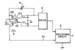
Please see the picture below. In some configurations the cap is replaced with a resistor which makes me think that the main purpose of the cap is to couple the signal back to the primary coil but I'm not sure why would anybody want to do that.
lvdt.JPG
 

Now the picture is clear. It is a classical circuit often used to sense linear position of a magnetic core inside a differential transformer. The core moves to change the coupling between the outer secondary coils in a complementary way such that the signals are equal and oppositive phase when balanced in the center position. When the core position moves in the opposite direction when driven with a sinusoidal current source, it generates a voltage whose amplitude is proportional to a position offset and the phase indicates direction from center.

The real answer for what item 4 is is only known to those skilled in the arts of sensing the unconventional schematic logic symbol. Logically it looks like a 6 toed sloth inverted in a tree acting as an antenna. My guess is that this invention is not to measure the displacement of the core, but detection of proximity of said 6 toed sloth ( with a magnetic tag on it's toe) near the LVDT. The variable capacitor Cv ( labelled incorrectly Vc, for the sake of lawyers) is used to tune the null position of all magnetic coupling to the both secondary coils so the result of driving a sinusoidal current from right to left ( See DRIVER BOX) in the center driver coil results in a balanced NULL on the outer differential voltage amplifier (inside the DRIVER BOX) . Any magnetic tags that increase the coupling of bottom outer coil can now be sensed with great amplification ( or sensitivity in psychological terms) to detect the presence of 6 toed sloths.

The purpose of the circuit was most likely written befuddled legalese patent slang so that people without the "skill in the arts" can only be amazed by its complexity.

So short answer is differential transformer tuning cap. to create a null center position.


My guess is the reason is to detect offset external magnetic proximity that interferes with the delicate balance of Vc to "null" differential amplitudes of two complementary signals on the secondary coils. hence the magnetic tag on the 6 toed sloth, designated as item 4.

The long explanation above is an anecdotal "Dave Berry" type reverse-engineering analysis.
 
Last edited:
I completely agree with the explanation. Nobody would have guessed from your posts that you are talking about a LVDT. It's very different from a "basic transformer".

It's a patent application diagram. Isn't the purpose of "Vc" exlained in the description text? You could also tell the patent number.
 

SunnySkyguy,

You are absolutely right about the circuit!!! This particular lvdt is not used to measure the displacement of the magnetic core but rather to sense the permeability of magnetic material 6. The Vc cap is indeed used to tune the operating window of the circuit without adjusting the magnetic core of the lvdt. It's pretty clear to me how the circuit works. What I'm trying to understand is the effect of that capacitor in a basic transformer. How does the coupling coefficient changes with introducing that cap to the circuit. An equation that would describe the relationship between the cap and the coupling coefficient in a transformer. What would happen if the cap was replaced by a resistor?
 

In simple words, neither a capacitor nor a resistor can change the coupling coefficient of a transformer.

It's a parallel circuit of a transformer and another element. The resulting output voltage can be calculated as superposition. You have to know the transformer windings ratio and leakage inductance for the calculation.
 
@Danst I believe the fixed load caps on each secondary coil serve to boost the signal sensitivity and voltage with a tank resonant circuit. The variable cap adds a bit for nulling purposes without loading down the Q factor or gain. Hence not a resistor. But if the amount was small it might also work.
 

Status
Not open for further replies.

Part and Inventory Search

Welcome to EDABoard.com

Sponsor

Back
Top