Continue to Site

Welcome to EDAboard.com

Welcome to our site! EDAboard.com is an international Electronics Discussion Forum focused on EDA software, circuits, schematics, books, theory, papers, asic, pld, 8051, DSP, Network, RF, Analog Design, PCB, Service Manuals... and a whole lot more! To participate you need to register. Registration is free. Click here to register now.

find the equation of RC network with transistor

Status
Not open for further replies.

baby_1

Advanced Member level 1
Joined
Dec 3, 2010
Messages
415
Helped
1
Reputation
2
Reaction score
1
Trophy points
1,298
Activity points
4,277
Hello i have this circuit
3_1336116455.gif

and i solve with this equation
gif.latex

is it correct?
and could you tell me an equation that join E and Capacitor Voltage? or E and Base Current?

Thanks
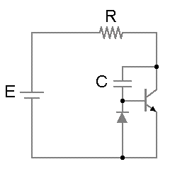
 

You should definitely make some assumptions for this circuit to keep the math managable.

If |E| <0.7V, the transistor will do nothing. When E >> 0.7V (starting from zero) , you can ignore the voltage drop across BE. In that case the transistor works as a current amplifier (Ic = Ib*HFE as rough approximation) Current through C (going down) will result in C*HFE A going down in the collector.

The effect is that the VCE will rise about HFE time slower then with the capacitor alone. The transistor operates as a "capacitor multiplier".

For E <<0.7V (starting from zero). the voltage will drop to about =-1.4V (that is diode drop of external diode and the drop of the BC junction in the transistor). Here the transistor doesn't amplify current.

As I don't see HFE (or related parameters) in your equation, it is very likely wrong (I can hardly read the equation).
 
  • Like
Reactions: baby_1

    baby_1

    Points: 2
    Helpful Answer Positive Rating
In usual circuit notation, E symbolizes a constant battery voltage. To change the problem in something more meaningful, we would either insert a switch symbol or a pulse voltage source.

According to known transistor behavior, the expectable waveforms can't be described by simple exponential functions. By making simplified assumptions like fixed Ube, constant current gain B, an approximate slution can be calculated. The problem specification would normally tell about allowed/suggested simplifications.
 
  • Like
Reactions: baby_1

    baby_1

    Points: 2
    Helpful Answer Positive Rating
Thanks
you assume that E is more than .7 such as 12 could i have a equation that show me the relationship between e and ib?
 

Firstly I would insist on an unequivocal problem specification, e.g. the voltage source is switched on at t=0 with discharged capacitor (Vc = 0).

Then the transistor + capcitor circuit can be replaced by a series circuit of a diode (voltage drop Vbe = 0.7 V) and a "multiplied" capacitor B*C.
 

Baby,

and i solve with this equation
is it correct?

What are you trying to solve? You just posted a term. Where is the equation? How can anyone answer the question?

and could you tell me an equation that join E and Capacitor Voltage? or E and Base Current?

If you can find i(t), you can easily calculate all those other voltages.

Setting up the loop equation, we get R*i(t)+(β+1)*1/C*∫i(r)*dt = E

Solving the above differential equation we get i(t) = (E/R)*exp(-((β+1)*t/(R*C)))

EDIT:

Sorry everyone, but I gave you the wrong solution. The node equation is (V(t)-E)/R+C*(diff(V(t), t))*(β+1) = 0 , where V(t) is the voltage on the collector. The solution is V(t) = E*(1-exp(t/((β+1)*RC)) . So the transistor increases the time constant by β+1 .

Ratch
 
Last edited:
  • Like
Reactions: baby_1

    baby_1

    Points: 2
    Helpful Answer Positive Rating
Thanks Ratch
i write this equation
gif.latex

gif.latex

gif.latex

gif.latex

could you tell me how did you solve the differential equation(sorry)?
and why you multiply the beta+1 to the equation of Capacitor ?why you don't add to R Current equation?
 

β is proportional to Ib and Tj until limit then β drops quickly and is inversely proportional to Vce near saturation. Both events occur at initial condition. If you get a "ballpark figure" aka a rough estimate on this atypical use, you are doing well. Then after the Capacitor charges up, it only becomes active for positive ripple on E or until negative ripple base diode clamp gets active, so it becomes asymmetric and noisy with .7Vpp ripple.

Another Capacitance Multiplier circuit, maintains bias for the transistor and puts the Cap on the base to ground in an emitter follower type, the cap is always active but has a 0.7 V drop. to Vo.
Cap-mult-q.svg


A darlington with a β = 1000 near sat. can make your 1,000uF into a supercap 1F and give less noise with low ESR and low cost.
 
Last edited:
  • Like
Reactions: baby_1

    baby_1

    Points: 2
    Helpful Answer Positive Rating
baby,

could you tell me how did you solve the differential equation(sorry)?

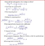
OK, just this one time. Eventually, you are going to have to learn to solve differential equations, whether by the classical method, LaPlace method, or a differential equation solver program. V(t) is the voltage at the collector of the transistor. Follow the method in the attachment.

and why you multiply the beta+1 to the equation of Capacitor ?why you don't add to R Current equation? .

The terms of the equation are what they are from the node equation and the differential equation solution. Other than being alert for errors, I don't try to second guess what the results turn out to be.

Capture.JPG

Ratch
 
  • Like
Reactions: WimRFP

    WimRFP

    Points: 2
    Helpful Answer Positive Rating
Bravo Ratch,
so for V(t)
V(0)=0 and for t=βRC=T
V(T)=63%*E

So as WimRFP & FvM said, you have a Time constant of βRC and then it operates on positive ripple only as I indicated.
 
  • Like
Reactions: baby_1

    baby_1

    Points: 2
    Helpful Answer Positive Rating
Status
Not open for further replies.

Part and Inventory Search

Welcome to EDABoard.com

Sponsor

Back
Top